Mimir Capabilities
|


|
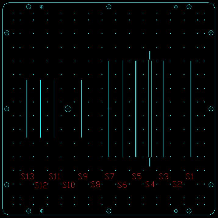
Mimir operates in three main modes: Imaging, Spectroscopy, and Polarimetry. In addition, there are three distinct "cameras" that may be selected for use within Mimir: the wide-field (F/5) camera; the narrow-field (F/17) camera; and the Pupil Viewer camera. In spectroscopy mode, there are 13 different slits, opens, and darks that may be inserted at the first focus. A review of the Mimir optics is found by following this link. The Mimir detector is a 1024 x 1024 InSb Aladdin III device which is sensitive to light from 0.6 to 5.6 microns wavelength. It features 17.8 electrons read noise, a conversion gain of 8.21 e/ADU, and well depths of 62,000-98,000 electrons per pixel. The dark current is about 10 electrons (1 ADU) per second per pixel for long exposures (100s). A listing of all 33 current Mimir operating modes may be found here. ImagingIn the imaging mode, the slit and decker cars are withdrawn from the beam, providing a full open field for the 10x10 arcmin square (3.66 x 3.66 inches) entrance to the collimator unit. Filters are selected from the filter wheel list either using available commonly-used scripts or by direct selection. Filter bandpass plots and data are also posted. Finally, the final plate scale and field of view are selected by commanding either the F/5 or F/17 cameras into the beam. The capabilities for these two plate scales are summarized in the following table:
L' and M' imaging may also be done in "row-by-row" reset mode. This limits efficiency, but permits use of the full F/5 field of view. [Cookbook on this is TBD.] SpectroscopyIn spectroscopy, one slit is selected, the decker is centered to select only the chosen slit, filters and grism dispersing elements are selected, and a camera is selected. With three different grisms, each with multiple orders, two cameras, and many filters the number of distinct spectroscopy options is quite large. Some of the most common and most efficient options are listed in the table below. Note that all slits are oriented North-South and instrument rotation is not allowed.
Detector maps and efficiency plots are also posted. Spectroscopic efficiencies (throughputs) and example spectra will be calculated over the next few months and posted here. PolarimetryIn imaging polarimetry mode, the POL wheel is moved to select a rotateable Half-Wave (either the H-HWP or K-HWP zero-order devices), the Molectron Wire Grid, and the proper bandpass filters. The HWP modulates the plane of linear polarization while the wire grid performs the analysis. Obtaining polarimetric data consists of obtaining a set of images, each with a unique position angle for the HWP. The HWP will introduce an intensity modulation with a frequency four times the HWP rotation frequency (a "4-theta" modulation). Extraction of the polarimetric signal, and calibration against known standards, is handled by our custom software. In this mode, the entire 10x10 arcmin field is available when using the F/5 camera or the entire 3x3 arcmin field when using the F/17 camera. Scripts to obtain polarimetry data are efficient and robust. The HWP position angle steps between images by 10.8 degrees, using a U, Q chopping mode to collect 8 U-Q sets of data per HWP rotation. This mode is encorporated into a 6-position dithering script that collects all polarization data while performing small motion (~15 arcsec) 6-position dithering on the sky. Polarimetric efficiency has been measured to be 91.1+/-0.45% and the instrumental polarization is low (0.05-0.45+/-0.02-0.04%) on average, with a field dependence. DPC 20101231 |
Quick Look Tables:
Quick Look Images & Plots:
|
|
|