RIPS
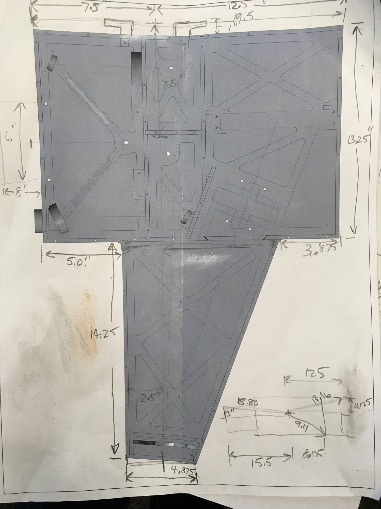
Topdown dimensions.
Topdown dimensions.

Front plate diagram.
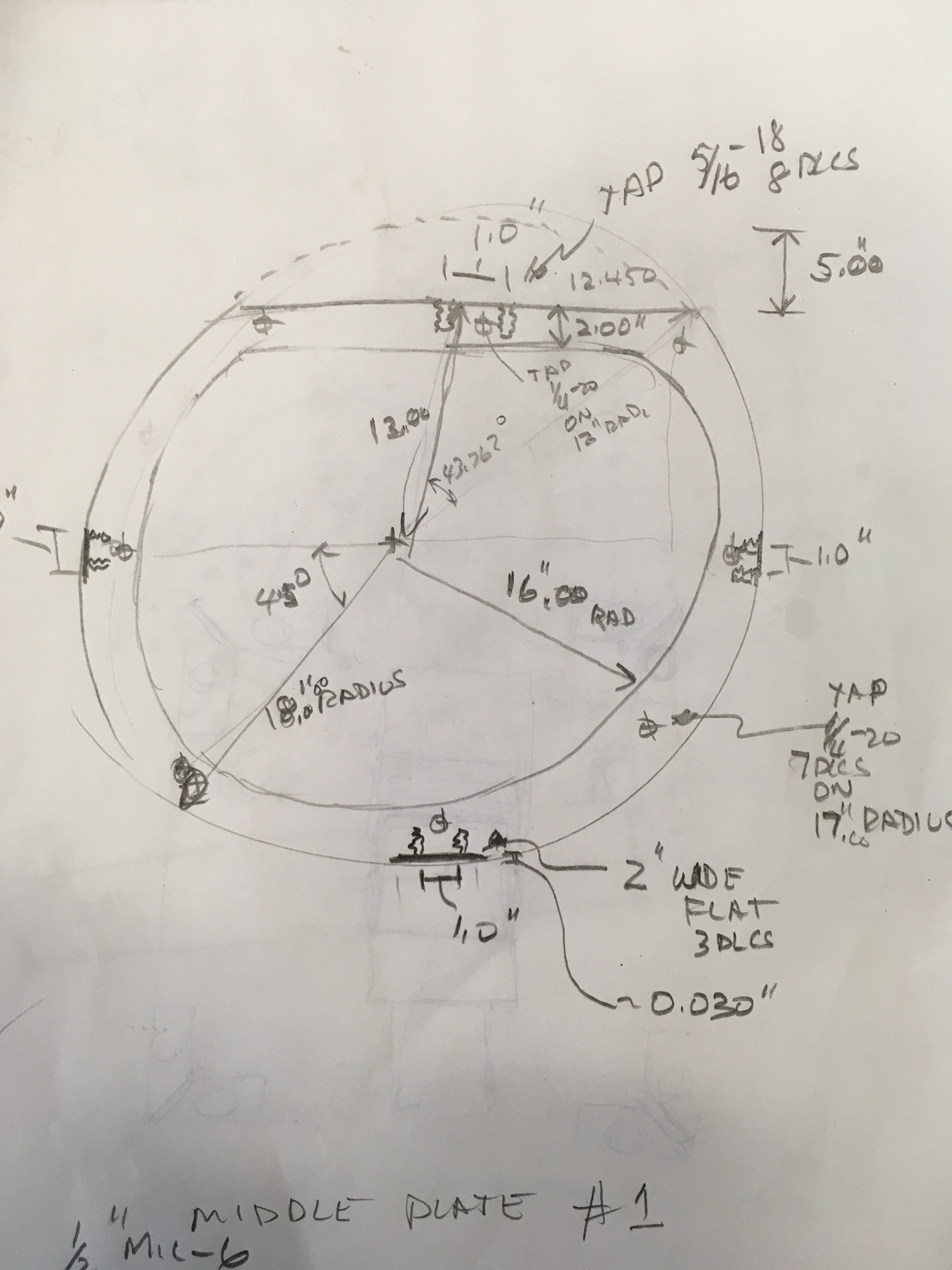
Middle plate diagram.

CAD drawing of RIPS in rotation cage.
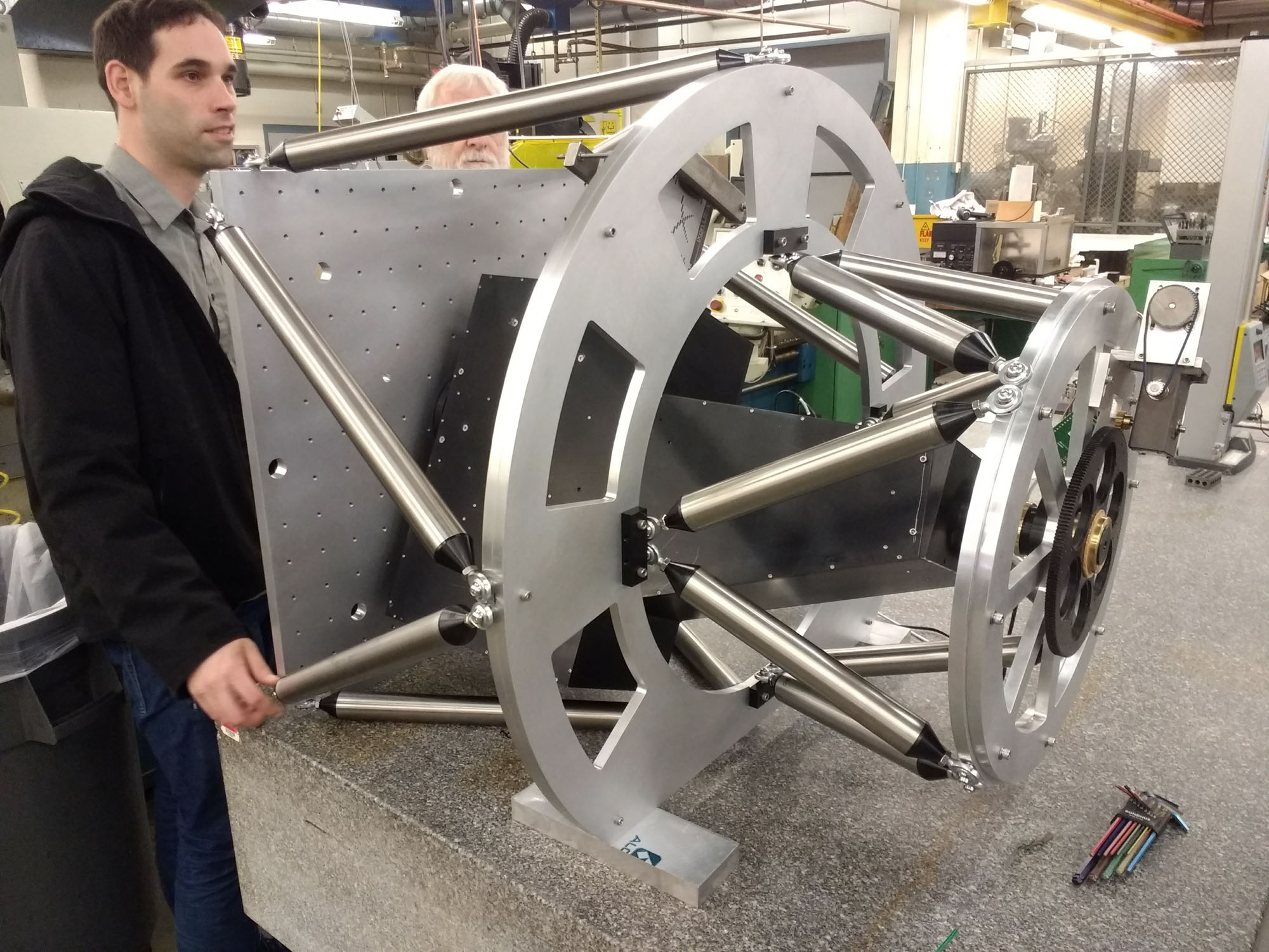
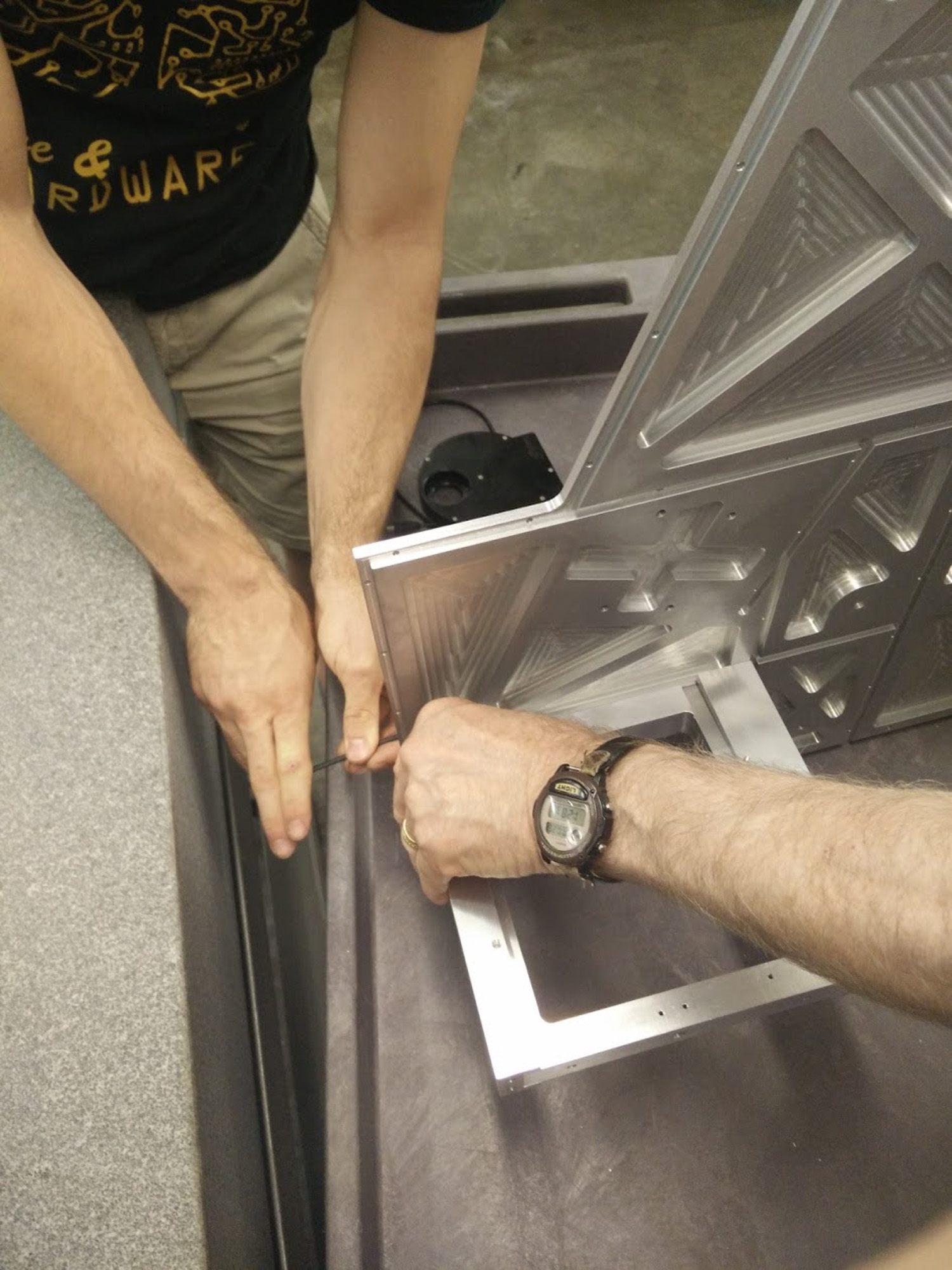
First full assembly in BU Scientific Instrument Facility.
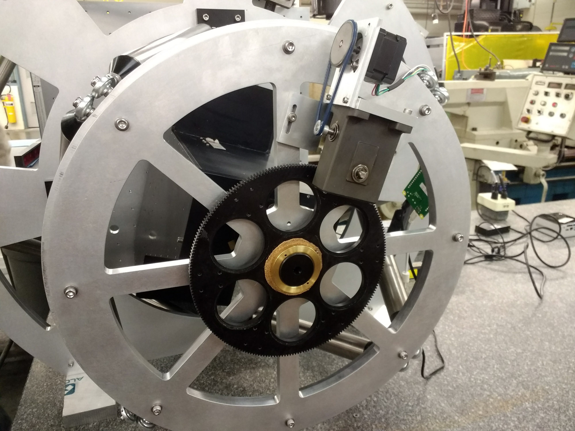
First full assembly in BU Scientific Instrument Facility.
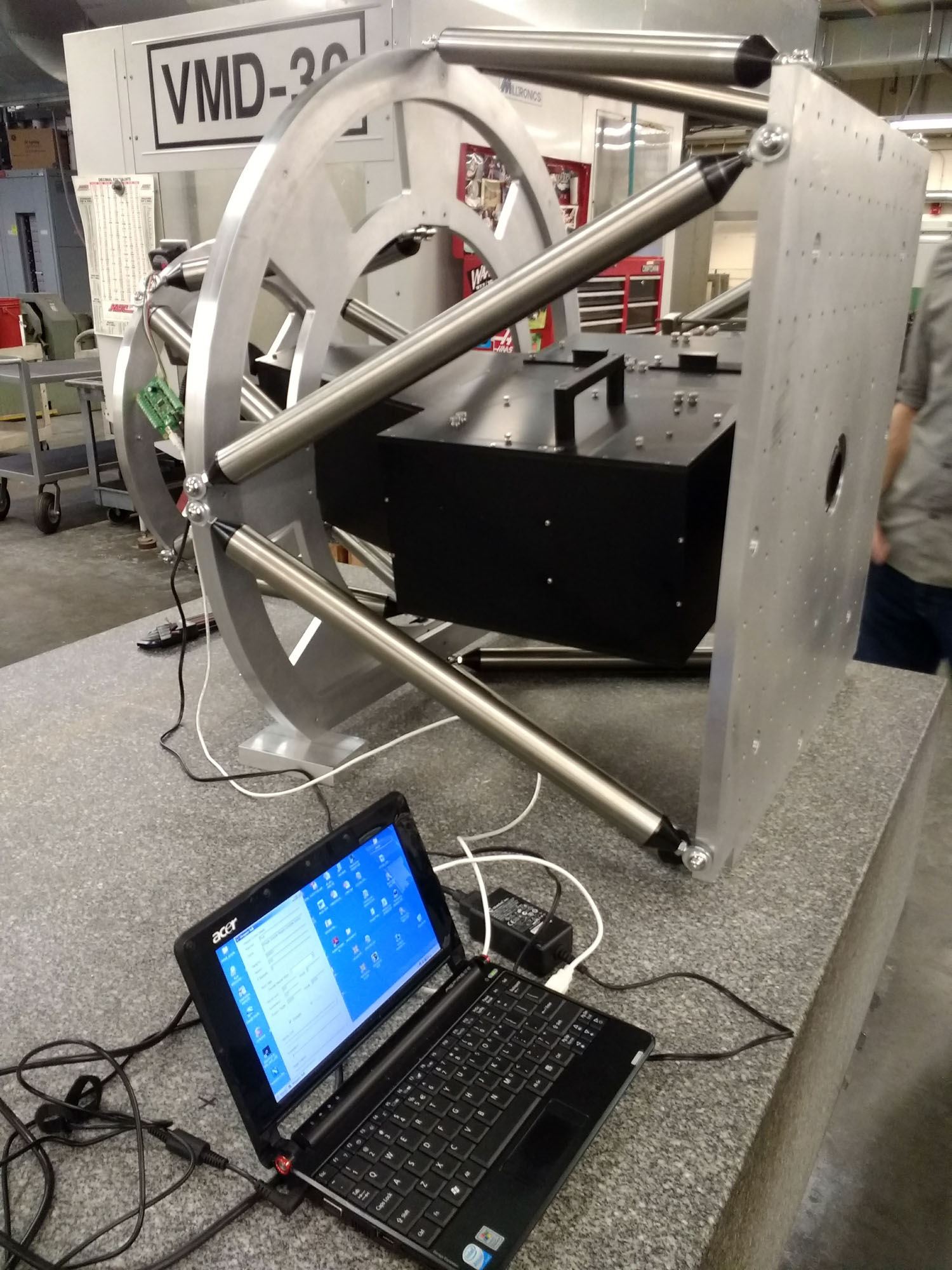
First full assembly in BU Scientific Instrument Facility.
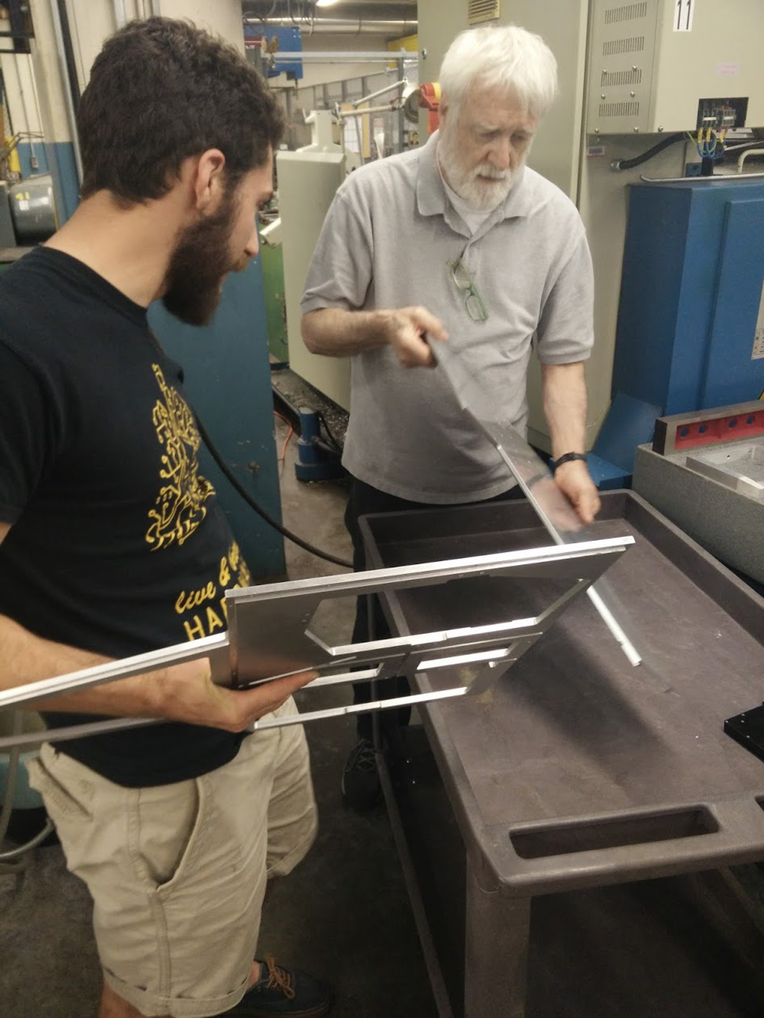
First metal cut at BU Scientific Instrument Facility.
First metal cut at BU Scientific Instrument Facility..
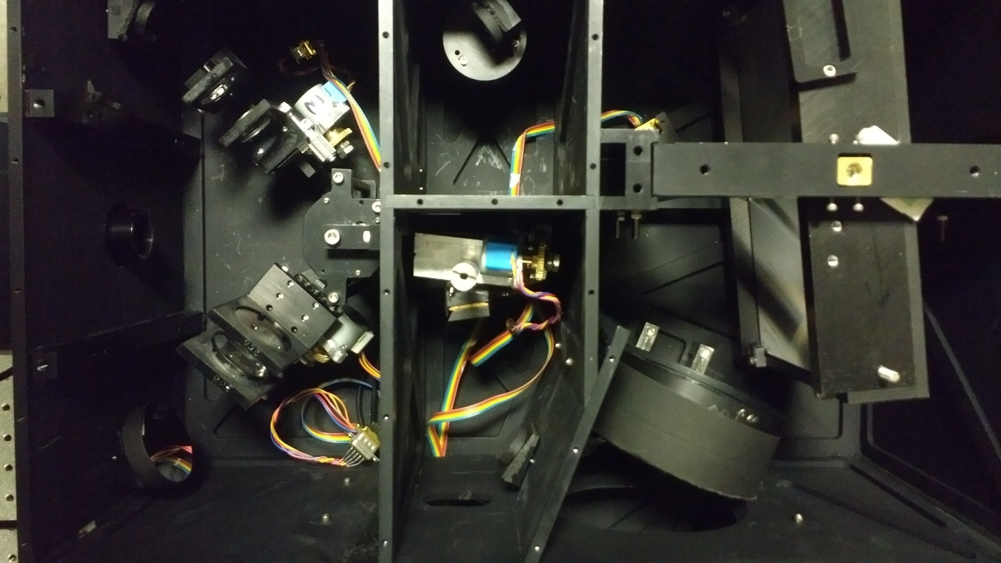
Topdown view of RIPS in BU Imaging Science calibration lab.
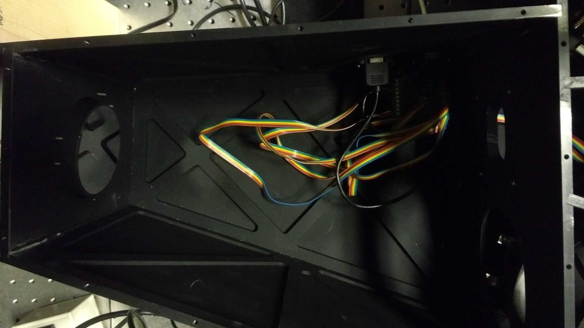
Topdown view of RIPS in BU Imaging Science calibration lab.

Isometric view of RIPS in BU Imaging Science calibration lab.
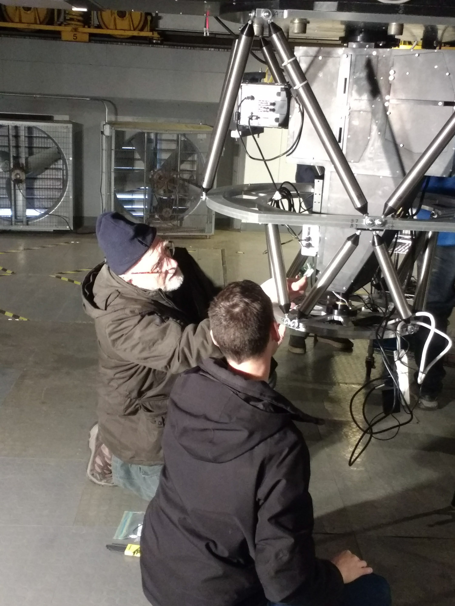
RIPS being installed on the 1.8m Perkins in Flagstaff, AZ.
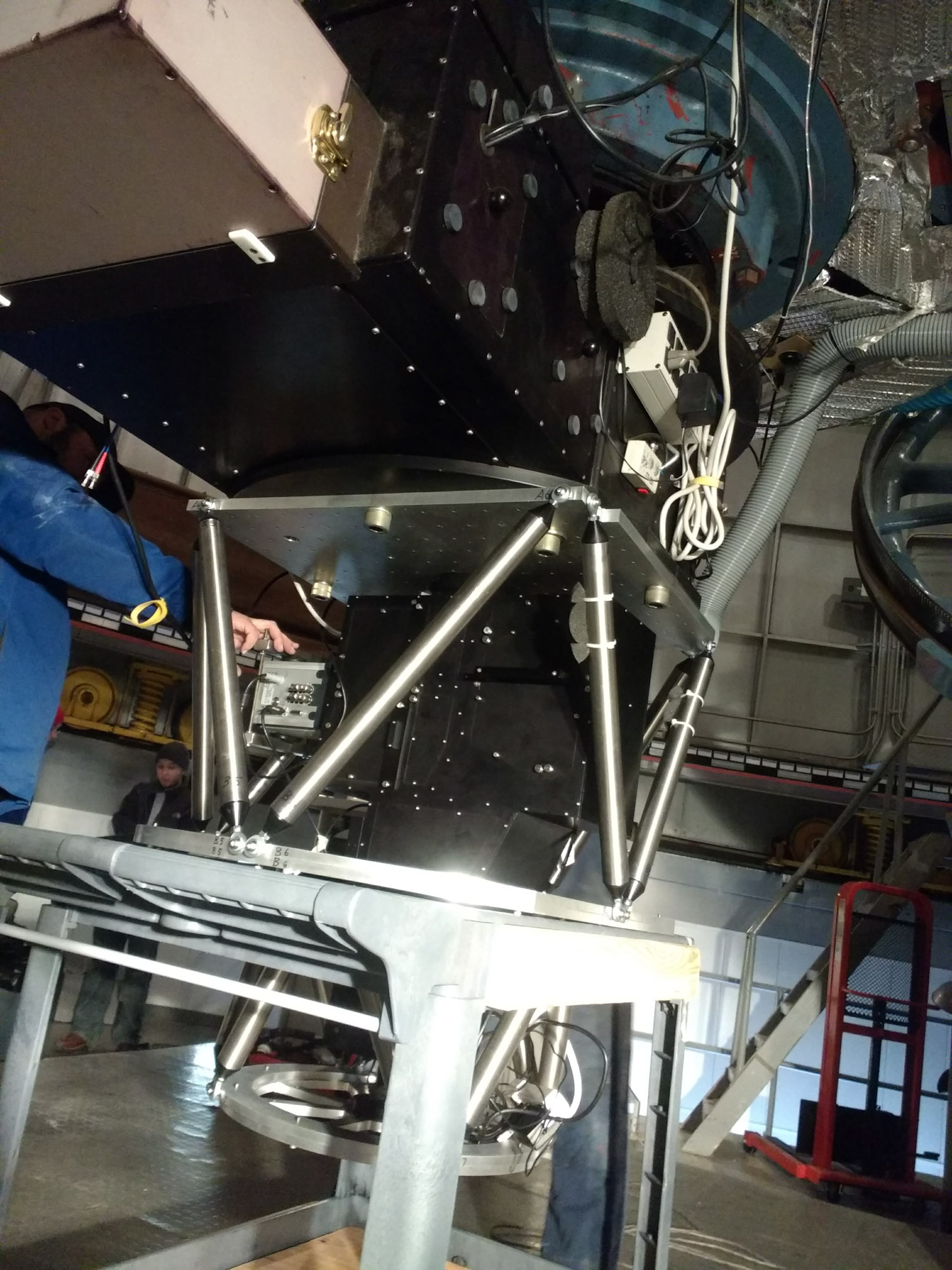
RIPS being installed on the 1.8m Perkins in Flagstaff, AZ.
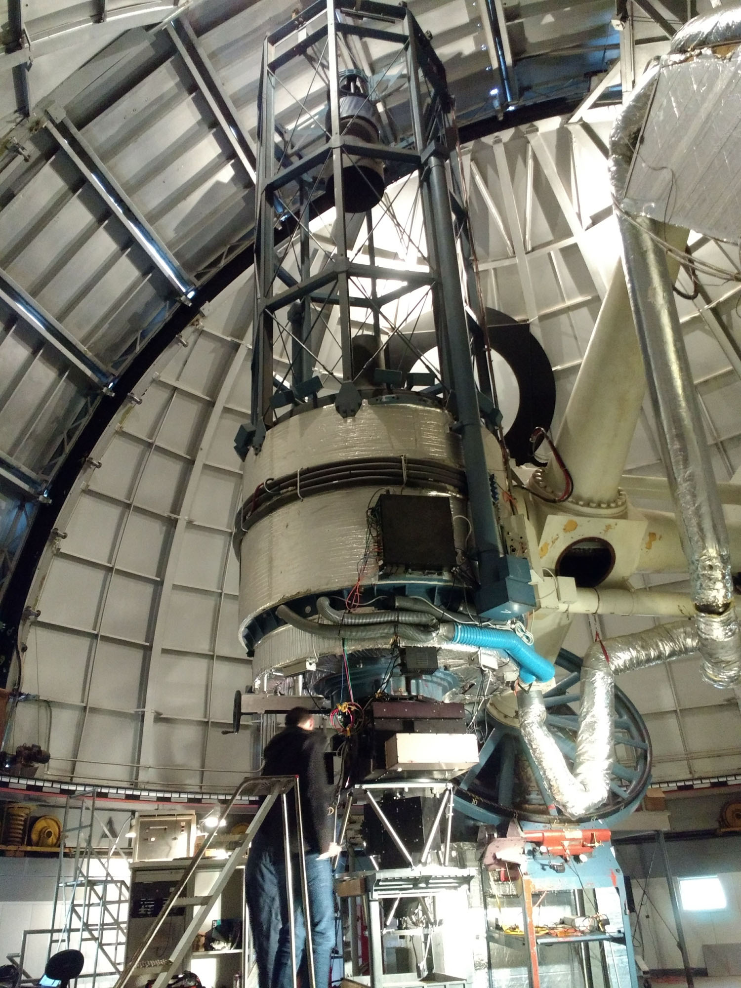
RIPS being installed on the 1.8m Perkins in Flagstaff, AZ.

RIPS being installed on the 1.8m Perkins in Flagstaff, AZ.
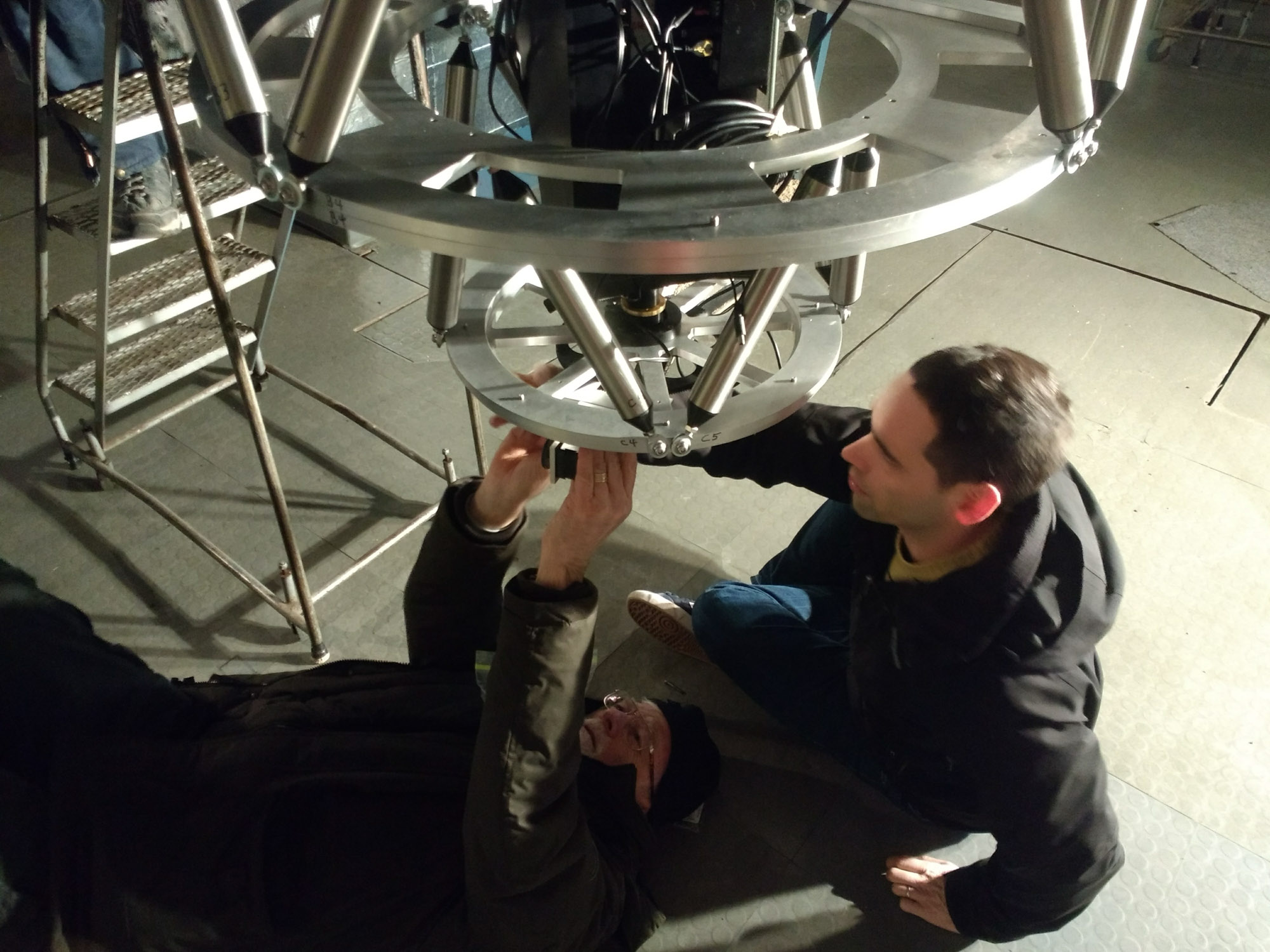
RIPS being installed on the 1.8m Perkins in Flagstaff, AZ.
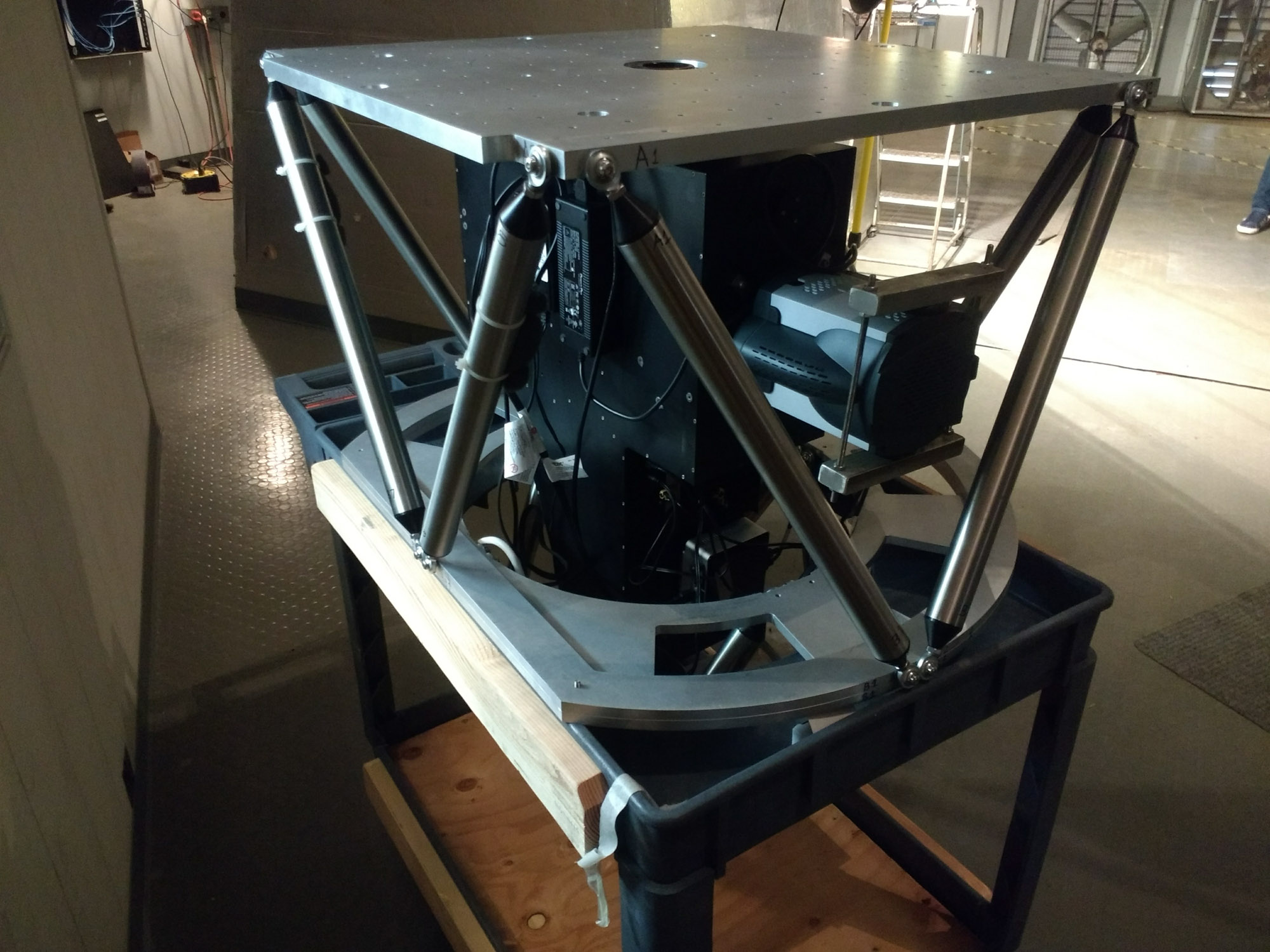
RIPS sitting in its cart after its first light run on Perkins.
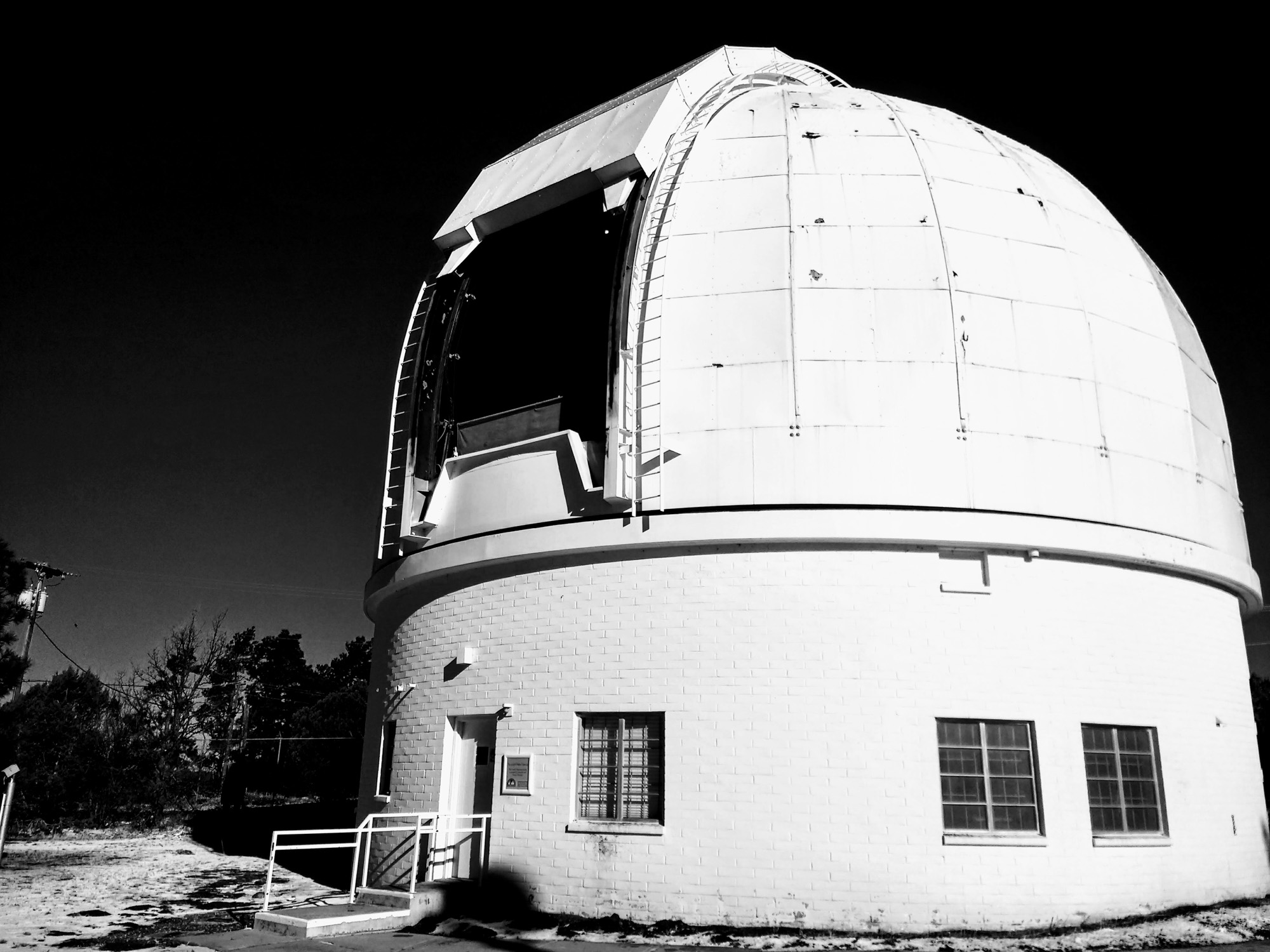
The Perkins dome outside of Flagstaff, AZ.

Morning after the first night of RIPS observations at Perkins.
| These videos show (left) raw frames, along with (right) "white light" images of Mercury's disk (using a relatively narrow Na pre-filter) and Na spectral images of Mercury's exosphere (i.e., constructed by extracting the processed spectrum frame-by-frame). At Perkins, the motion of RIPS' slit across Mercury is due mostly to various undesired telescope motions (e.g., from wind and jitter). At AEOS, however, the telescope's adaptive optics system helps us to "lock on" Mercury, which enables us to control the motion of the slit across Mercury's disk, leading to a much smoother sampling. Nevertheless, the addition of enough frames in either case allows for a reconstruction of the spatial distribution of Mercury's Na exosphere.