|
During the week of March 6-12, Mimir was serviced in the clean room on
the first floor of the Perkins telescope building. Key goals for this
servicing were to:
- replace the pupil mask with one based on pupil viewer images taken
in December,
- move filters to better support J+LM spectroscopy,
- add a second Ks filter,
- modify the cold strapping so to reduce the detector heat needed,
- replace or rewire failed thermal sensors,
- implement a secondary backup heater/sensor for the refrigerator 2nd
stage,
- remove the MLI between the 3 stainless steel floating thermal shields
forward of the cold bulkhead,
- inspect and evaluate the decker unit's operation,
- inspect the filter, camera, and detector bays for aluminum dust and
chips
A short report may be found at this
link.
The full disassembly and inspection report (including all pictures) may
be found at this
link.
Some representative pictures from this servicing follow...
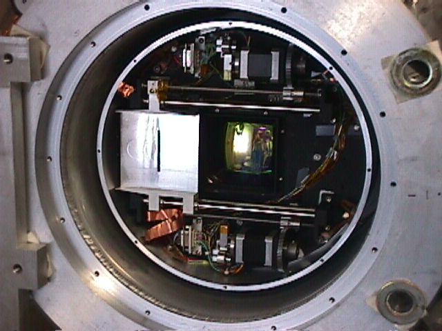
 Mimir insides, after removal of cryostat shell and cold shield. Black
box holds filter bay, camera bay, and detector bay. Getter is silvery,
perferated cylinder - detector thermal strap system originates in getter
then sweeps around to detector bay. Camera motor/brake system sticks out
from camera bay (under detector thermal strap).
Mimir insides, after removal of cryostat shell and cold shield. Black
box holds filter bay, camera bay, and detector bay. Getter is silvery,
perferated cylinder - detector thermal strap system originates in getter
then sweeps around to detector bay. Camera motor/brake system sticks out
from camera bay (under detector thermal strap).
 Decker/slit
unit with cryostat front cover removed. Silver square with vertical slot
is the decker car, slit car is hidden under it. First collimator lens
is seen in center, under square box baffle unit. Decker and slit cars
ride on steel rods, driven by lead screw and stepper motor system. Motors
feature detent units with reed switch sensors. Decker/slit
unit with cryostat front cover removed. Silver square with vertical slot
is the decker car, slit car is hidden under it. First collimator lens
is seen in center, under square box baffle unit. Decker and slit cars
ride on steel rods, driven by lead screw and stepper motor system. Motors
feature detent units with reed switch sensors.
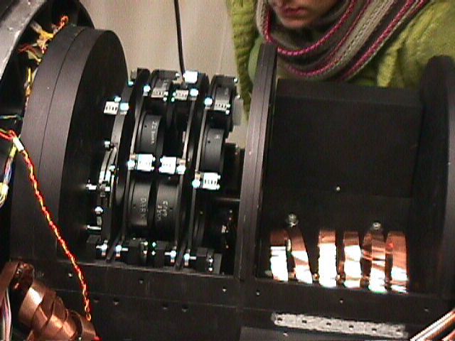 Covers
removed to show filter bay (left, with three filter wheels and one half-wave
plate wheel) and camera bay (camera block black anodized, connected to
outer box with copper thermal straps). Covers
removed to show filter bay (left, with three filter wheels and one half-wave
plate wheel) and camera bay (camera block black anodized, connected to
outer box with copper thermal straps).
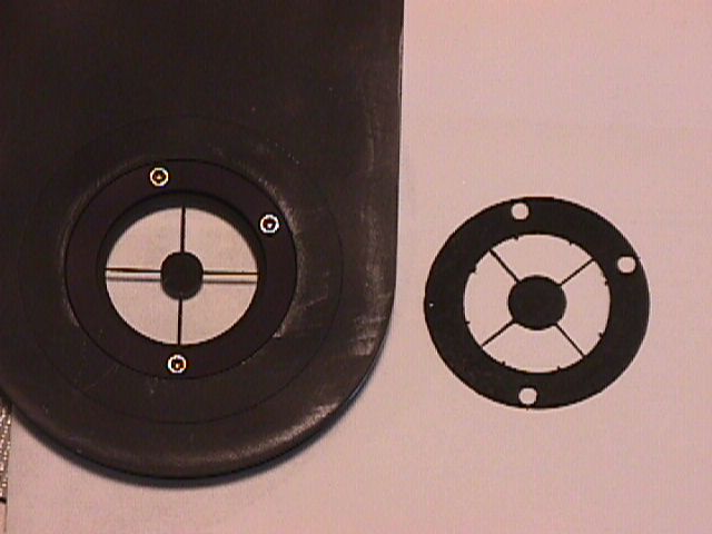 Pupil
Mask holder, with original pupil mask and new pupil mask (right) based
on December 2004 observations with Mimir's internal pupil viewer. Pupil
Mask holder, with original pupil mask and new pupil mask (right) based
on December 2004 observations with Mimir's internal pupil viewer.
Marc took some higher resolution pictures of the pupil mask and holder.
To view them, click on one of the thumbnail images below:
 New
pupil mask in holder (click on image to see full resolution picture). New
pupil mask in holder (click on image to see full resolution picture).
 Zoom
of new pupil mask (click on image to see full resolution picture). Zoom
of new pupil mask (click on image to see full resolution picture).
The actual pupil image used as the basis for the photoetching of the
mask was obtained in December 2004 and is shown below:
 Pupil image from Mimir's Pupil Viewer camera. Click thumb to see full
sized version. Note that the dark shadows are caused by the old pupil
mask. It failed to match the secondary support spiders locations, inadequately
masked the outer diameter of the primary, and failed to mask the stovepipe
and secondary structure in the center region. The eight "tabs"
sticking in from the outside were a surprise to everyone, but were included
in the new pupil mask. The thin dark horizontal line in the upper right
quadrant is an artifact of our detector crack and not the pupil mask.
Pupil image from Mimir's Pupil Viewer camera. Click thumb to see full
sized version. Note that the dark shadows are caused by the old pupil
mask. It failed to match the secondary support spiders locations, inadequately
masked the outer diameter of the primary, and failed to mask the stovepipe
and secondary structure in the center region. The eight "tabs"
sticking in from the outside were a surprise to everyone, but were included
in the new pupil mask. The thin dark horizontal line in the upper right
quadrant is an artifact of our detector crack and not the pupil mask.
|


