August 2005 Mimir Servicing |
||
|
During the three week period of August 2-18, Mimir was serviced by DC and MB in the clean room on the first floor of the Perkins telescope building. Key goals for this servicing were to:
Along the way, several minor goals were also achieved:
Some items on our goals list were not completed or deferred to the next servicing:
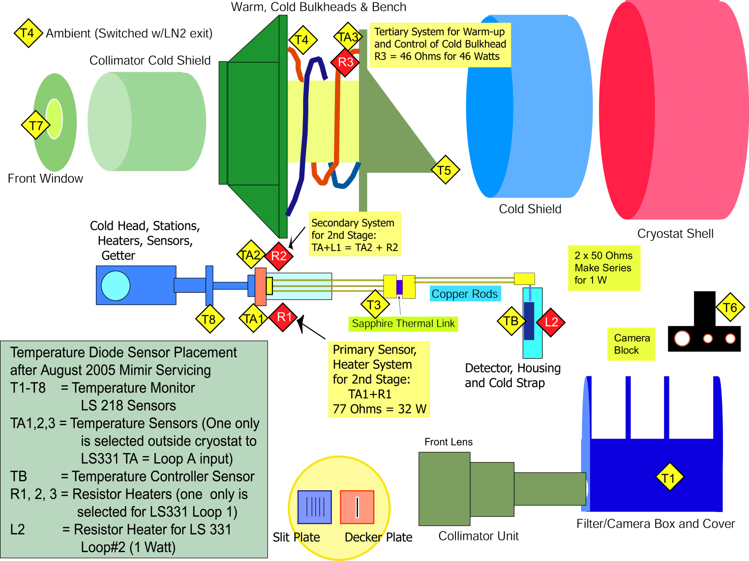
Inspection Report - On opening Mimir and the filter bay and camera bay, no medium or large size metal chips were found, and the amount of aluminum "dust" was minimal. The detector volume was also free of any chips and also had only minimal aluminum dust (barely enough to wipe off with a finger). We noted no new locations scoring or rubbing of the camera block against the back (or front) camera bay bulkheads. This lack of evidence of interference of the camera block with its bay changed the nature of our approach to fixing the stalled camera motion problem - the electromechanical brake became the target of our repair efforts. Camera Motion Unit Repair - After the March 2005 servicing, during which we tightened up the springs holding the camera block to the THK rail car and the springs holding the THK rail to the base of the camera bay, the camera again failed to move when tested cold in July (in fact, it stalled at a position not on one of the camera boresights). Though we expected to find interference of the camera block and the camera bay bulkheads, this was not the case. Instead, we found that the electromechanical brake, when disengaged still produced too much resistance to allow the motor to drive the camera block. After dismantling the brake unit, we settled on four modifications, all designed to allow the THK shaft to rotate freely with the brake disengaged. First, we had pockets cut in one side of the moveable brake plate to allow the three push springs to have about 35 mils more room. This decrease in the compression of the springs gave somewhat smaller force pushing the moveable brake plate against the rotating brake pad when the brake was engaged, as we judged this force was quite excessive compared to that needed to keep the camera block from freely moving when the motor power was removed. This decrease in the spring force also allowed us to increase the throw of that moveable brake plate, that is, it could travel farther from the electromagnet and yet still be able to be pulled back to the electromagnet to disengage the brake. Without reducing the spring force, an increase of only 5 or 6 mils in travel was too far for the electromagnet to pull the plate back to disengage the brake. Second, we polished both the moveable brake plate and the fixed brake plate with 600 grit paper to produce a near-optical finish. This helped reduce the brake friction, especially in the disengaged setting. Third, we added 3 mils of shim spacing between the two brake plates to give the rotating brake pad disk more room to rotate freely (especially as it is tilted on its shaft). Finally, the set screws that located the rotating brake pad disk were set to allow the pad disk to freely rotate in the disengaged position. Previously, a significant preload was put on this pad so that even in the disengaged setting there was some friction between the pad and one brake plate. At present, when disengaged, the brake rotates freely with no friction applied to either plate. In the engaged setting, the brake can slip if considerable force is applied to the camera block (in excess of 30-40 lbs), but we believe the brake will be able to hold the camera block in place even with the THK rail pointed vertically (the orientation with the maximum gravitational force on the 18 lb camera block). Movies were taken of the camera block moving between the "home" position and the positions corresponding to the bore sights of each of the three cameras in the camera block. The AVI-type movie showing the motion from home to the f/17 (narrow field camera) position is found at this link. Filter Wheel Encoder Change - the old filter wheel encoders consisted of units for each wheel with 3 (for the pol wheel) or 4 (FW1-3 wheels) magnetic reed switches mounted tangent to each wheel. These would sense the presence or absence of small Samarium-Cobalt magnets in holders positioned at each filter position. Each magnet holder was manufactured to hold a unique 3- or 4-bit code for each filter position by the presence or absence of magnets in the holders. The old design stacked the reed switches in each encoder parallel to the direction of the optical axis and the magnets were positioned end-on to the centers of the reed switches. This method proved difficult to tune and was unreliable to cooling and instrument orientation. New sensors and magnet holders were designed that were much less sensitive to orientation changes of the instrument, easier to tune, and we expect will be better able to cope with temperature induced CTE changes in the filter wheel stack. Reed switch holders were designed and machined at Lowell Observatory. These mostly fit in the same footprint as the old reed switch holders. The new holders accept new, tiny circuit boards on which surface mount reed switches are attached. These new, tiny reed switches were not on the market when Mimir was being developed -- their new availability allows for smaller packaging with much greater current handling capability (350 mA vs the < 10 mA of some of the reed switches still in Mimir -- TTL currents are typically 27-35 mA, which required LS-type current levels before). We also rotated the reed switches so each one is parallel to the optical axis, but each set of 3 or 4 are staggered around a portion of the circumference of each filter wheel. The new magnet holders (manufactured at the BU SIF) put the magnets parallel to the switches, also staggered around a portion of the circumference. This magnet-parallel-to-reed-switch orientation is the preferred way to operate these switches and results in much better sensitivity, larger allowed magnet-switch physical separations, and because both magnet and switch are parallel to the filter wheel shaft, much more tolerance of orientation driven sags and offsets. The switches close whenever one of the magnets is within 0.2-0.25 inch, so the magnet-to-magnet and switch-to-switch distances are set to 0.35 inch. Tuning was done by starting with full length magnets in each magnet holder to realize the desired bit code, and then breaking off pieces of the magnets to remove excess cross-talk (closing of neighboring reed switches that should not have been closed). The unmodified dimensions of the magnets are 72 mils dia by 0.4" length. Generally length reductions by 1/3 were adequate to achieve robust code generation with no cross-talk. After magnet tuning, all magnets were cemented in place using Sytcast 2850 with Catalyst 23 (the preferred low-temp combination). Instrument Grounding System - A coherent evaluation of the grounding of the instrument and its two electronics rack had not been done previously, yet we were concerned about excess noise seen in the images when off the telescope, sparks produced when the pumping station was attached, and general concern about lightning protection. A detailed evaluation of all units in Mimir was undertaken and some surprises emerged. As it had been configured, there were no ground connections from the main electronics rack to the Mimir cryostat and from the array controller (aka "the Leach electronics") to the cryostat *except* when all were mounted on the telescope. Further, the shields on the temperature monitor and control cables were floating at both ends. We also found that the helium lines served to connect the ground for the 220 V 3-phase compressor power to the 110 V single-phase "clean" instrument power through the cryostat. There is also some indication (which needs to be tracked down in November) that there are two ground wires going from the Leach electronics A/D boards to the Aladdin III detector substrate. We attached significant ground straps between the cryostat and the electronics rack and between the cryostat and the Leach electronics. The temperature monitor and control cables had their shields grounded at the electronics rack, what was already being done for all the motor cables and the vacuum monitor cables. We plan to tie the new helium hard copper lines to the new shed ground cable which is buried in the new trench between the telescope building and the compressor shed. A new connector (BNC instead of the old SMA-type) pair was installed for the HV line of the BA gauge to improve reliability of both the signal (the old cable had a habit of pulling out of the connector at the back of the electronics rack) and its shield ground. We also purchased and will install an isolation transformer between the clean instrument 110 V power and the Leach electronics to try to remedy the first read dropouts that still have plagued about 3% of the images taken. We believe noise on the 110 V is leading to TTL upsets within the Leach electronics and expect the isolator to cure this problem. New Helium Compressor Shed and Piping - Until this servicing, the helium compressor was located within the telescope dome, connected to the cryostat cold head by a combination of flex hoses and stainless steel hard pipe draped on the telescope floor. This temporary system well served the initial year of testing of Mimir on the telescope, but needed to be replaced by a permanent configuration that put waste heat outside the dome and more safely routed the helium gas supply and return lines. During the spring, a concrete pad was poured on the ground outside the telescope building's north side. A metal shed was erected over the pad in mid-summer. During this service period, the compressor was moved into the shed. New power lines were brought into the shed, and twin hard copper pipes were put in place to span from the side of the new shed, into the telescope building, up onto the observing floor, and on up to the top of the north telescope pier. The lines were purged and pressure tested at 300 PSI. Gas expansion/reservoir units were fabricated from small, "lecture-size" bottles into "T" type configurations, with opposite gender Aeroquip pressure fittings at the ends of the Ts. These units were placed at each end of each of the supply and return helium lines to absorb the pressure changed induced by the operations of the valves in the cold head. When the entire system (compressor, expansion units, hard lines, flex lines, and cold head in the Mimir cryostat) was tested, the cold head showed wonderful cooling power and the noise level was much reduced (the noise level at the cryostat is now less than that of an average inkjet printer!). The flex lines that connect to the hard lines at the top of the north pier will be bundled with the cold head motor power cable into a reroutable umbilical cable that will attach to Mimir while on and off the telescope. Cleaning of Cold Head - As part of the new helium shed testing, we thought we uncovered a problem in the refrigerator cold head on the cryostat. To ascertain the cause, the head was partially disassembled while still on the cryostat. The motor/gearbox unit was released from the stainless steel flange unit that holds the two cold stations, and the displacer piston was pulled from its SS cylinder. That is, we pulled the cold head "guts," while keeping the cryostat under vacuum. The displacer was indeed dirty, as it had not been serviced for at least 10,000 hours of use. The displacer was cleaned with acetone, as was its SS cylinder. The gearbox was dismantled and also cleaned with acetone. All pieces were reassembled and installed back into the cryostat. Though the root cause of the apparent problem was traced to a wiring change in the 220 V 3-phase power going into the compressor shed, removal and cleaning of the cold head components will insure a longer period of trouble-free operation this upcoming year. And, now that we know we can remove the cold head guts while leaving the cold stations intact, this will likely become a normal yearly servicing task. Insulated one 2nd Stage Temperature Sensor - For several cold runs, we have seen the silicon diode temperature sensor attached to the 2nd stage (10K stage) of the refrigerator fail deep into each run (weeks or months into the runs). The mode of the failure is to cease to read the 12-14 K of the 2nd stage and to instead drop down to either about 5K or all the way to 0K. If the second stage is heated beyond about 50K, the sensor seems to return to fairly normal operation. Different diodes were swapped out of that location, but the problem repeated. During the March 2005 servicing, we added a backup silicon diode sensor to the 2nd stage (along with a fully redundant heater to the first heater), to try to ascertain whether the problem was in the sensor or in the wires to the sensor. In the cold run since March *both* sensors failed (sequentially) deep into the run. This time, one of the sensors was modified to make it electrically insulated from the 2nd stage. Kapton tape was put under the sensor and the sensor was attached to the second stage heater block with a nylon screw. The redundant sensor was left in electrical contact with the 2nd stage heater block. While the 2nd stage temperature is not controlled during normal cold operation of Mimir, thermal closed-loop control of this stage is needed for dealing with anomalies (like power outages that require a getter bake out and quick vacuum pumping before returning to normal operations). Camera Block Temperature Sensor Installed - The camera block contains the lenses making up the three cameras (F/5, F/17, PV). The camera block is thermally attached to the filter box mostly through a set of 18 thin, flexible copper straps (see the movie above). This copper strapping system causes the camera block to lag thermally behind the filter box and the rest of the optics during cooldowns. This is likely a source of high backgrounds seen by the detector, until the block can cool to the 65-75K operating temperatures. Additionally, as the camera bay (which is part of the filter box) cools, it contracts. A slower cooling camera block will contract slower and this differential contraction rate could reduce the clearances between the camera block and the camera bay bulkheads to zero during cooling. Until this servicing, we have had no temperature sensor on the camera block to monitor the block's cooling. The T6 sensor was therefore moved from being located just outside the detector box to the top of the F/5 camera part of the camera block. The new sensor placement cartoon diagram can be found by clicking on the thumbnail below.
Adjusted Filter Wheel Stack - During the past cold run, there were several instances of the POL wheel and the FW3 wheel not reaching commanded filter positions. Inspection of the filter wheel stack showed that the POL wheel runs too close to the first bulkhead, and with the instrument pointing to zenith, that clearance runs to zero for some positions of the wheel. The filter wheel stack position is set by a spacer ring between the final bearing race and the back filter box bulkhead. A 15 mil shim was added to push the stack closer to the front of the instrument. This solved the POL wheel interference problem, but introduced failures in the FW3 wheel, as it now interfered with its bulkhead (and especially with the part of its bulkhead located in the filter box cover). The 15 mil shim was reduced to a 3 mil shim as a compromise. The POL wheel still occasionally misses steps on its way to some positions, but mostly at zenith. A complete cure will be attempted during next year's servicing. The filter wheel stack will then be disassembled and shims added to put more total space between the POL and FW3 wheels, allowing both some more separation from their respective bulkheads. This a major undertaking, so was deferred from this August servicing. With the encoder system more robust, it was judged acceptable to miss some POL steps for some positions and to jog the motor until the proper detent is found. Filter Wheels Balanced - The filter wheels are not all full of filters and we had attempted to distribute the filters in each wheel to achieve roughly balanced filter wheels. However, at least two of the wheels (FW2, FW3) were not well balanced by this approach. Unbalanced wheels make the detent action non-uniform and even somewhat unrepeatable for different directions of arrival for a given filter (CW vs CCW). Balanced wheels are also less likely to stall if interference is encountered. To balance the wheels, the detent arm was pulled back and the wheels allowed to rotate freely. Filters were moved on the wheel, and dummy filters added, until wheel balance was achieved for all wheel rotational positions. The new filter positions may be found by clicking on the thumbnail below.
|