 |
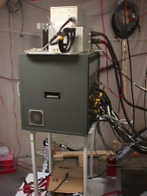
Electronics box in Perkins clean room, with ARC array control electronics on top |
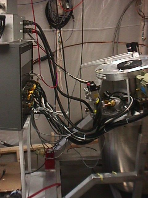 |
Cabling to cryostat in clean room |
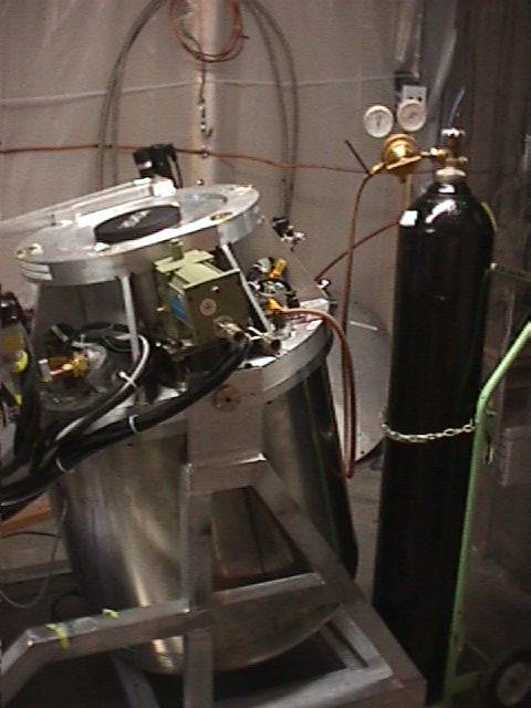 |
Dry N2 gas backfill system. Mimir is back filled with N2 prior to opening to try to keep water out of the 120 layer MLI in the thermal blanket that resides just inside the SS outer cryostat shell. |
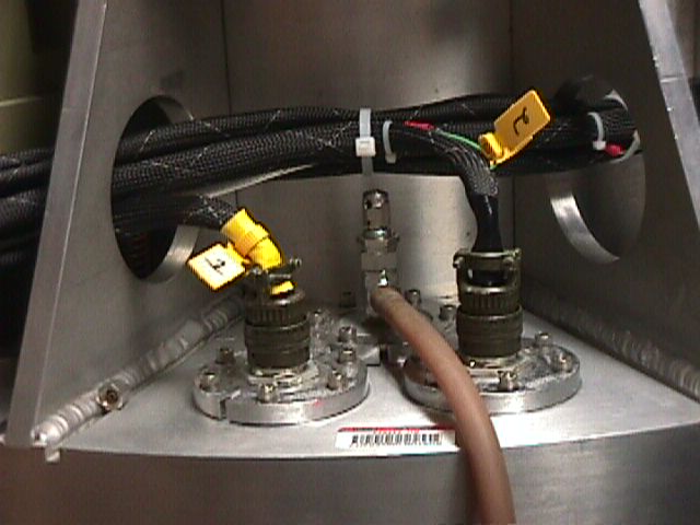 |
Needle valve on Mimir warm bulkhead. This valve was used to throttle the rate of N2 backfill, but was later found to be a source of vacuum leak itself and was decommissioned. |
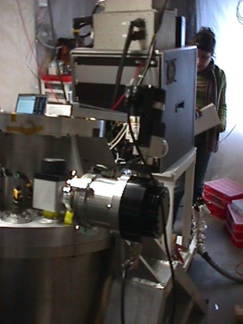 |
Turbo pump mounted on NW40 vacuum valve on warm bulkhead. |
 |
Electronics, cryostat, and warm bulkhead heater control. |
 |
Detector connector headers on warm bulkhead |
 |
Using grounding wrist straps when handling detector cabling. |
 |
Detector wiring shorting plug - red side installed first |
 |
LN2 exit port, with pressure relief blow valve. |
 |
Electronics rack, front view, CCR cold head |
 |
SS cryoshell cart - four of these wheels contact and support the shell when it is off Mimir. |
 |
SS cryoshell cart, shell not present. |
 |
LN2 input port to pre-cool loop in the cold bulkhead. This vacuum pumping arrangement was used to clear the line of any LN2 and to prevent air from getting in an freezing when Mimir was at operating temperatures. Unfortunately, this vacuum system was not perfect, and the mech pump used allowed pump oil to cryopump into the pre-cool loop inside Mimir. This led to a spectacular problem in later years. |
 |
The twin instrument cart system. The larger cart at left supports Mimir on and off the telescope. It also has a cable and winch system to allow Mimir to reorient to a 90 degree (horizontal) configuration. When in this config, the small cart at right is inserted under the cryo shell. The shell is released from Mimir and the small cart conveys the shell away for closure and vacuum pumping to keep the MLI layers of the thermal blanket clear of water. |
 |
Instrument cart winch system used to reorient Mimir to the horizontal position. Shell cart is being inserted under the shell (the two carts "nest" one into the other). |
 |
Back view of the twin carts and Mimir's horizontal orientation. |
 |
Ring bolts that secure the SS cryo shell to the warm bulkhead. A large O-ring is captured in a groove in the warm bulkhead to provide vacuum integrity. |
 |
Mimir SS cryo shell, on its small cart, with the shell cover installed. This cover has an O-ring groove to provide vacuum integrity. The cover also has a single vacuum flange to permit pumping and vacuum sensing while the cryo shell is off of Mimir. |
 |
Edwards Wide Range Gauge (WRG) connected to shell vacuum system. Pumping not yet started, gauge at ATM. |
 |
Lifting out the front cover. |
 |
Installing handles into aft cold shield. These handles allow moving this large, heavy shield. |
 |
"Beefeater" MLI layers between the warm and cold bulkheads. This blanket was later replaced with a system of three SS collar plate shields. |
 |
Rear view of aft cold shield, showing mounting bolts holding the shell to the "Clemens Clamp" connected to the cold optical bench. |
 |
Mimir, as configured after removal of the SS cryo shell and the aft cold shield. Note the changes in the CCR 2nd stage to detector cooling system. The old "cold pipe" is gone, replaced with three 1/4" diameter copper rods. A new split, copper block unit is present midway along the cold path. This block includes a 1/2" dia sapphire disk, through which all heat flows, but which is a complete electrical insulator. Its purpose is to better electrically isolate the detector from the shell and any static electricity that might damage the detector array. |
 |
Oblique view, showing more of the new detector cooling assembly. |
 |
Detail view of detector unit. Note ribbon cables and thermal connection with silicon diode thermal sensors at top of detector unit. The threaded copper 1/4" bolt passes through a light-tight circuit board into the array mount unit. |
 |
Front cover MLI blanket, removed from Mimir. |
 |
Front thermal shield, with taped MLI |
 |
Front thermal shield, removed from Mimir. It consists of a thin G10 cylinder, wrapped with about 100 layers of MLI. |
 |
After removal of front cold shield, the front cover of the active cold shield, box baffle, and first lens of the collimator are seen. |
 |
Removing the front cover reveals the slit/decker system. In this instance, the cold straps to the decker and slit cars are still in evidence. In later rebuilds of Mimir, these are not used. |
 |
Detail view of thermal strap to slit car (located underneath the decker car, in this image). |
 |
Another view of the same zone. Note the copper lug attached to the inner face of the active cold shield with a 1/4" 20 screw and connected to copper braid. This thermal strap goes to the baseplate of the slit/decker system to improve its overall cooling. |
 |
Location of silicon diode thermal sensor on decker car. This sensor showed that strapping the cars was not necessary - they achieve cold operating temperatures without any additional thermal strapping. |
 |
Details of stepper motor, gear system, and detent unit for the slit car. |
 |
Motor shaft has been rotated to show position of the detent magnet arm when out of detent condition. The reed switch sensor can be seen under the end of the detent magnet arm. Kapton tape holds the magnet in place. |
 |
Detail view of the three copper 1/8" dia rods that carry heat from the detector to the CCR 2nd stage through the split copper and sapphire block. |
 |
Opened filter and camera bays. |
 |
Filters are held in place with V-shaped spring-loaded pieces pushing on the filter cell rims at two places and a slot for the rims machined into each filter wheel. An alignment pin at the front of each slot ensures the filters are rotationally located. The V-shaped pieces The hex driver shown is used to tighten the pieces against the filter cells. Each wheel position has its own 4-bit magnet stack that is sensed by the 4-bit reed switch encoders for each wheel. |
 |
The entire filter wheel system (4 wheels and nested hubs) is captured at the front and back of the filter bay using two split blocks that locate and capture two bearing races. |
 |
Very dark detail showing the filter wheel hub shaft and the split block used to capture the shaft (and its end bearing race) in the bay bulkhead. |
 |
The front of the four filter wheel nested hub system is a set of four gears, each driving a single filter wheel. These engage shafts and gears from four stepper motors bolted against the front bulkhead of the filter box. The motor shafts and drive gears are trimmed for length to enable driving only one wheel gear each. |
 |
Same zone, but seen from opposite side of instrument. Here the split block that holds the front hub shaft and end bearing race is seen in the upper right. The first wheel drive gear and motor shaft are seen at middle right. The roller bearing in the lower left is part of one of the POL wheel cell rotation systems. |
 |
Rear hub shaft capture block removed to show hub shaft, end bearing, and machined precision spacer. |
 |
Front gear system, showing one motor shaft with drive gear removed. Pulling the entire filter wheel system requires removing two of the motor drive gears to provide adequate clearance. |
 |
Pupil masks for Mimir. The installed pupil mask is the original one, based on information about the location and orientation of the telescope secondary spiders and size of the secondary blockage. These proved incorrect, so a new pupil mask was fabricated (at right, just prior to installation) with correct spiders and secondary blockage. Also note the 8 "teeth" on the new pupil mask. These represent incursions into the telescope beam by components of the primary mirror cover. The new pupil mask was developed using images provided by the Pupil Viewer camera within Mimir. |
 |
New pupil mask installed in the pupil mask holder. This mask was photoetched and spray painted with black paint, then baked. |
 |
New pupil mask being inserted into the second bulkhead in the filter bay. It resides on the optical axis between the last two filter wheels. |
 |
Inner bulkhead details, with pupil mask holder installed. |
 |
Split copper-sapphire block detail. Each half of the copper block is soldered to the 1/8" dia copper rods that carry heat from the detector. Note that during this servicing, one of the rods at right (going to the detector) was cut to reduce thermal conductivity (which was too high!). Between the copper blocks a sapphire disk is located and it provides all the thermal conductivity with no electrical conductivity. Block to block registration and compression is provided by four long nylon screws and cylindrical bushings. The screws are spring loaded using wave washers located under the screw heads.The exit side of the copper block system hosts a silicon diode thermal sensor. |
 |
Copper screw feedthrough at detector unit. Note the third copper rod has been clipped off here as well as at the copper block. This unit is also instrumented for temperature monitoring. Copper washers and a black epoxy covered G10 piece make up a thermal feedthrough that is light tight and electrically non-conducting. |
 |
Three new SS collar flats were added in place of the "Beefeater" MLI blanket. the flats are offset from each other by nylon screws into nylon bushings, forming a set of three thermall "floating" shields to intercept thermal radiation from the warm bulkhead before it reaches the cold bulkhead. Note how the LN2 hoses (still wrapped in MLI) are sandwiched between the new floating shields. |
 |
Copper getter heater block with resistive heaters and thermal sensors. |
 |
Another view |
 |
And another. |
 |
Cold bulkhead with smaller heaters (ones that can be driven by the LakeShore 331, instead of 110VAC) and thermal sensors installed. These new units permit modest warming of the instrument for "bake out" under vacuum to remove any water prior to final cooling. The old heater system did not permit closed loop operation. Interesting that a failure of a similar system in GNIRS killed that instrument. We deliberately designed the new heater capabilities for Mimir to not allow it to rise more than about 20C above ambient temperature. |
 |
Details of the new cold bulkhead heater (at left) and silicon diode thermal sensor (located away from the heater at right). |
 |
Getter with new copper getter heater (at right). Covering the face of the heater is the indium needed to ensure good thermal conductivity |
 |
Back of electronics rack showing new thermal heater and sensor options. Through these switches, closed loop control of the heating of the cold bulkhead or the 2nd stage could be controlled. Also, the 2nd stage getter heater had two sets of heaters and sensors, providing redundancy. |


