![](../images/photo_archives/2003/20030716/001_wire_grid_cell_face.jpg) |
Cell face to hold wire grid (grid not yet installed) |
![](../images/photo_archives/2003/20030716/002_wire_grid_cell_face_with_kapton.jpg) |
Kapton ring added |
![](../images/photo_archives/2003/20030716/003_wire_grid_cell_parts.jpg) |
Wire grid cell parts |
![](../images/photo_archives/2003/20030716/004_wire_grid_in_cell_half.jpg) |
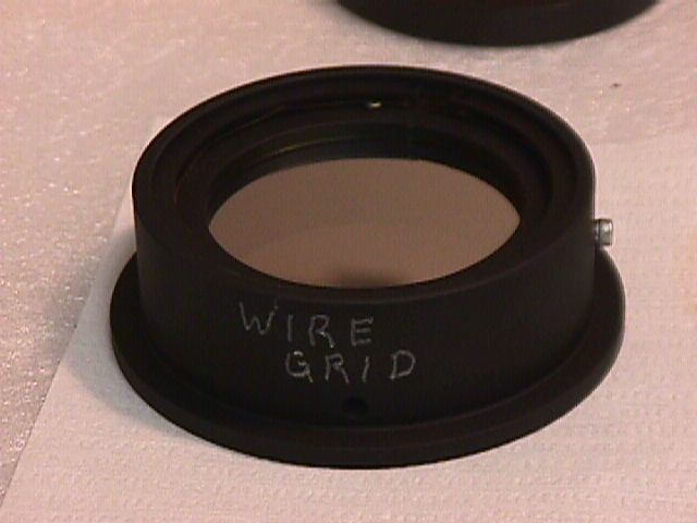
Wire grid (unmounted) in cell half |
![](../images/photo_archives/2003/20030716/006_wire_grid_cell_housing.jpg) |
Wire grid filter cell with grid cell installed |
![](../images/photo_archives/2003/20030716/007_wire_grid_housing_with_WW.jpg) |
Wave washer atop wire grid cell, in filter cell, about to be energized with C-ring |
![](../images/photo_archives/2003/20030716/008_wire_grid_unit_assembled.jpg) |
Wire grid cell, fully assembled |
![](../images/photo_archives/2003/20030716/009_HWP_cell_parts.jpg) |
Half-wave plate cell parts |
![](../images/photo_archives/2003/20030716/010_HWP_cell_halves.jpg) |
HWP cell halves |
![](../images/photo_archives/2003/20030716/011_HWP_cell_half_with_springs.jpg) |
HWP cell half with leaf springs |
![](../images/photo_archives/2003/20030716/012_HWP_cells_and_MgF2_plates.jpg) |
HWP cell halves with MgF2 plates, about to be mounted |
![](../images/photo_archives/2003/20030716/013_one_MgF2_plate_in_cell_half.jpg) |
One MgF2 plate installed in a HWP cell half |
![](../images/photo_archives/2003/20030716/014_two_MgF2_plates_in_two_cell_halfs.jpg) |
Both MgF2 plates in their respective cell halves. |
![](../images/photo_archives/2003/20030716/015_HWP_cell_halves_assembled.jpg) |
HWP cell halves, assembled. There is a thin kapton ring (1 mil?) separating the two MgF2 pieces. |
![](../images/photo_archives/2003/20030716/016_HWP_in_gear_cell.jpg) |
HWP cell mounted in geared filter cell |
![](../images/photo_archives/2003/20030716/017_HWP_in_gear_cell.jpg) |
HWP in geared filter cell, top view |
![](../images/photo_archives/2003/20030716/018_J-band_corrector_parts.jpg) |
J-Band Corrector parts. The optical design indicated that J-band would need a field flattener for the wide field F/5 configuration. This corrector flattens the J-band PSF variations (Strehl variations across the field). In practice, on the sky, we found no difference between using and not using the J-band corrector, so it has been decommissioned and removed from Mimir. |
![](../images/photo_archives/2003/20030716/019_J-band_corrector_lens_in_lens_cell.jpg) |
J-band corrector lens installed in lens cell. |
![](../images/photo_archives/2003/20030716/020_J-band_corrector_assembled_in_filter_cell.jpg) |
Fully assembled J-band corrector lens in its filter cell. |
![](../images/photo_archives/2003/20030716/021_collimator_fore_section_parts.jpg) |
Parts for collimator foreward section, and its assembly drawing. |
![](../images/photo_archives/2003/20030716/022_collimator_fore_section_with_L2_installed.jpg) |
Collimator forward section with L2 (BaF2) installed |
![](../images/photo_archives/2003/20030716/023_collimator_fore_section_with_L1_&_L2_installed.jpg) |
Collimator forward section with L1 and L2 installed. [installing L1 on top of L2 was done using bent piano wire to grasp the L1 cell in 3 places and then gently set the L1 cell in place.] |
![](../images/photo_archives/2003/20030716/025_DPC_in_collimator_reflection.jpg) |
Reflection of Dan Clemens in "antireflection" coating on L1 in foreward collimator section. |
![](../images/photo_archives/2003/20030716/026_DPC_in_collimator_fore_section_reflection.jpg) |
Another Clemens reflection in L1 |
![](../images/photo_archives/2003/20030716/027_collimator_fore_section_in_bell_jar.jpg) |
Completed collimator foreward section, in vacuum bell jar after assembly. |