In order to analyze voltage gated channels in axons, the squid giant axon has been the standard go-to preparation. However, most axons in invertebrate and vertebrate nervous system are very thin and often branch repeatedly. There is no easy way to analyze voltage gated channels other than the classical Vaseline seal method for myelinated axons, or, in a handful of preparations, by patching synaptic terminals. The crayfish opener neuromuscular junction has relatively large axons that allow for insertion of multiple electrodes. However, voltage clamping an axon is associated with two serious difficulties. First, it is impossible to achieve an acceptable space clamp in a long and thin cable such as an axon. Second, there is good reason to believe that the distribution of voltage gated channels in axons is often not uniform. As a result, the ideal situation is to voltage clamp just one section of the axon at a time. This article describes a little device our department machinist has designed and constructed that is able to delicately pinch and close off an axon of about 30 μm in diameter. I am hoping to use this devise, designated an axon pincher, to isolate one chuck of axon at a time and thereby perform voltage clamp.
|
|
|
|
Fig.1: Illustration of the space that holds the forceps. The arrow identifies the trough in which the forceps will be seated. The arrow head identifies the retention wall that keeps the forceps from sliding forward. |
Fig.2: Side view of the pincher. The upper arm of the forceps is visible, arrow. Forward movement of the slider, arrowhead, can close the forceps. |
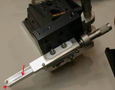
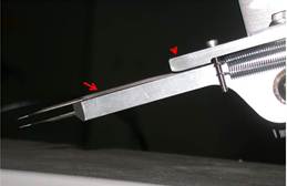
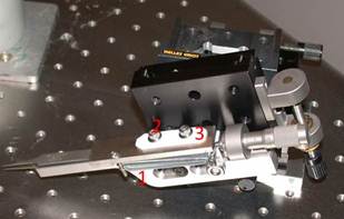
The axon pincher is designed such that a micrometer is used to slowly close a pair of fine forceps. The pair of fine forceps is dropped into a deep holding space made of aluminum, Fig.1 arrow. There is no fastening mechanism for the forceps; the downward pressure of a slider and the retention wall at the end, Fig.1 arrowhead, are enough to keep forceps stationary. The depth of the holding space is such that the top arm of the forceps rises above the edge of the holding space, Fig.2 arrow. A slider, Fig.2 arrowhead, is advanced by a micromanipulator and the forward movement gradually closes the forceps. The slider is spring loaded, Fig.2, and kept on a straight track by slots and machine screws, Fig.2. Two pieces of Teflon, above and below the slider, are used to reduce friction, Fig.3. The entire devise is mounted on a three dimensional manipulator, Fig.3, so that I can maneuver the forceps under a 60X water lens.
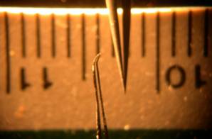
There isn't much space under the 60X water lens, and axons are much thinner than the sharpest pair of #5 forceps. It is therefore necessary to customize the shape the forceps tip. First, it is necessary to make each tip of the forceps thinner on the Z-axis, to reduce the entire height of the forceps such that they can fit within the 1.5 mm working distance of the water lens and still have room to move. Second, it is necessary to give each tip a slight bend such that the forceps can come in with a shallow angle and have more room to maneuver. Third, it is also necessary to make the forceps narrower otherwise the width of the forceps will take up half of the field of view under a 60X lens. Forth, I find it better to shape the end of the forceps such that the lower tip is slightly longer and can "scoop up" the axon before closing the pinch. Figure 5 shows a side by side comparison of a custom-shaped pair of forceps and a new pair of Dumont #5. Finally, it seems to be necessary to use forceps made from the right kind of material. Dumont produces more than five variants of #5 forceps, each made from a different kind of alloy. I have the impression that some alloys are too soft and cannot pinch axons properly after they have been thinned and narrowed. Forceps made of Dumostar, one of the harder alloys, work fine.
|
|
|
|
Fig.3: The axon pincher as mounted on a 3-D manipulator. This figure also show: (1) the springs that hold back the slider, (2) the machine screws that guide the forward movement of the slider, (3) the Teflon sheets that ensure smooth movement of the slider. |
Fig.4: A shaped pair of forceps on the left and a new pair of Dumont # 5 on the right. The scale behind them shows 10 to 11 centimeters, so each subdivision is 1 millimeter. |
Acknowledgement: Although I had the idea for such a devise some time ago, it never materialized until I spoke about it with our machinist, Jonathan Perry. He alone is responsible for the design and fabrication of this device. Here is Jonathan: