 |
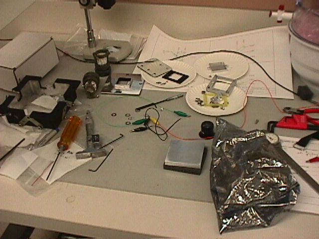
Parts for the array mount. Many came from MKIR, the remainder were custom fabricated at BU. |
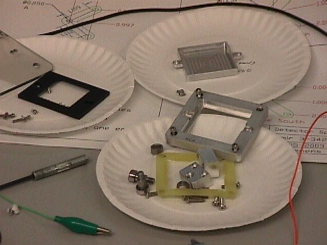 |
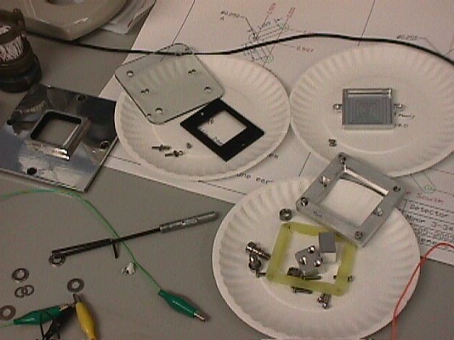
Details of the array mount spacer, cover, baffle (at left), and a dummy array cover (at top). |
 |
At left is the rifled baffle snout that covers the array mount unit to provide light control to the array surface. The short snout sticks through the back side of the camera bay back wall. |
 |
Array mount from MKIR, absent detector array and attachment hardware. |
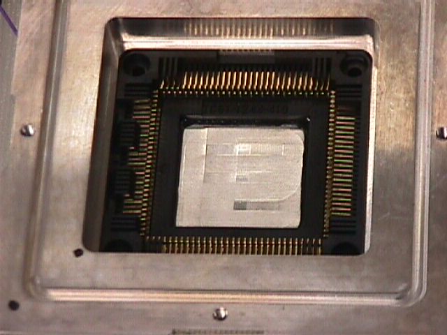 |
Details of the array socket, showing contact fingers that lead to connections going to the fanout board (not seen here, located inside the array mount unit). |
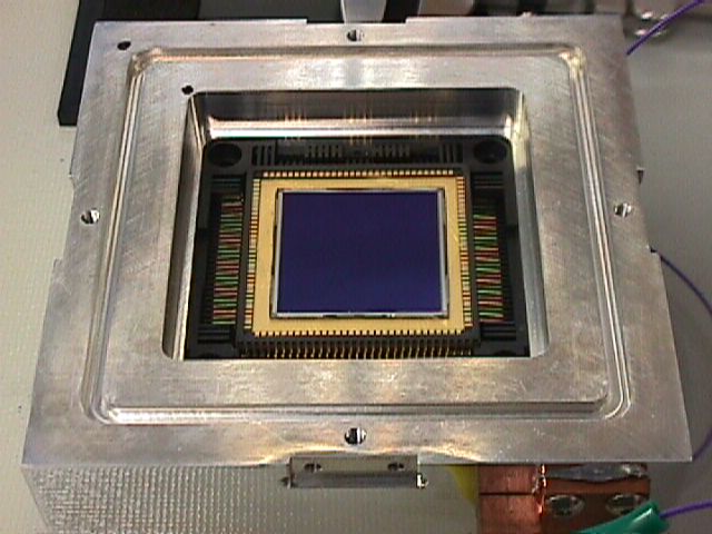 |
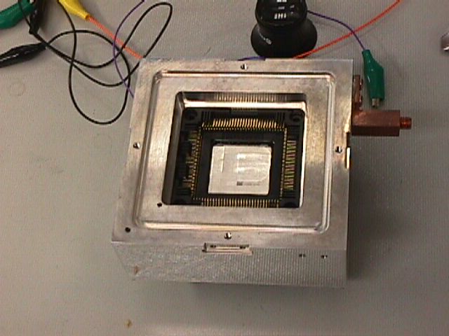
Our ALADDIN III science array, located in the chip socket, but not tied down. A few of the 1 mil gold bond wires can be seen connecting the (black) array to its substrate connectors. |
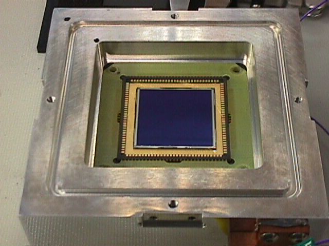 |
Another view, this time with the G10 array "locator" installed. This G10 piece positions the array substrate (through its socket, it appears) and covers the sensitive socket wiring. |
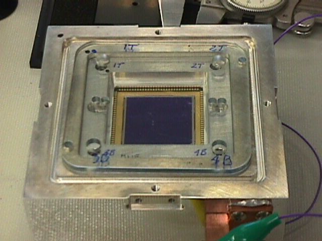 |
After installation of the aluminum inner cover (over the G10 locator) and a temporary plastic protective cover. The numbers and letters identify the array quadrants out from the chip to, eventually, the wiring. |
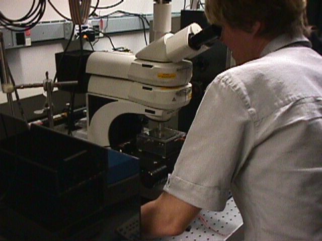 |
Dr. Anna Swan, in Prof. Bennett Goldberg's device lab in the Photonics building, using calibrated microscope to locate our science array relative to known surfaces in the detector housing. |
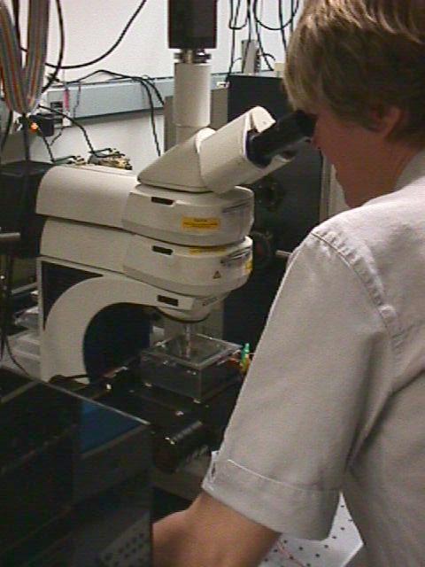 |
Another view of Dr. Swan and the Mimir detector unit |
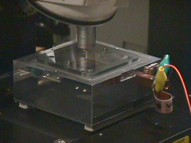 |
Array mount with microscope optics during metrology |