 |
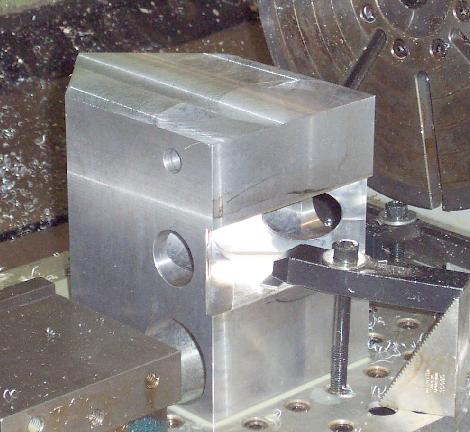
Camera block,
after holes bored, top peaked, and bottom F/17 bay opened up. the
bore holes, are, from bottom to top, the F/5 camera path, the F/17
camera path, and the pupil viewer camera path. |
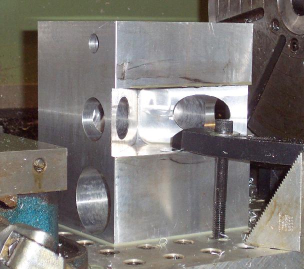 |
Underside view
of camera block. The F/17 dogleg bore holes are just visible. They
allow the much longer F/17 camera path to be folded using four mirrors
into the camera block space. |
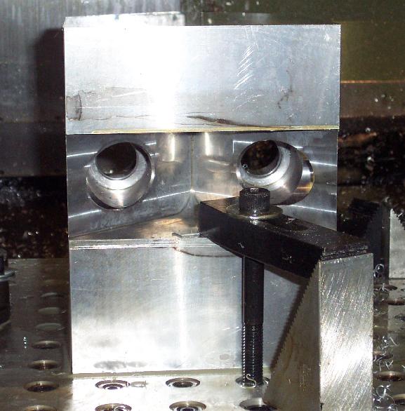 |
View from bottom
of Camera block to show bore holes for F/17 folded beam path. Inside
the bore holes are flat reference surfaces against which lens cells
are mounted. Inside all the bore holes, anti-reflection "rifled"
baffle tubes are snugly fit. These control stray light in this confined
beam path. |
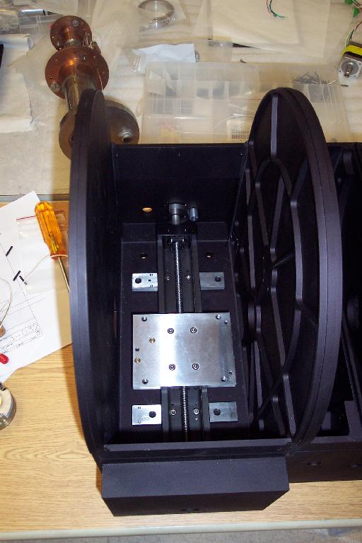 |
THK lead screw
drive system (aka "rail") mounted to the bottom of the camera
bay in the filter box. The two rectangular aluminum bars under the
THK rail hold the ball bearings and sockets comprising a 3-point kinematic
mount. The square aluminum plate on top of the rail is bolted to the
two "cars" that ride the rail (one car captures the screw,
one car is free of the screw). This plate also has sockets for a 3-point
kinematic mount |
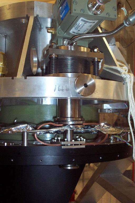 |
Cold head mounting details. CTI 1050 refrigerator motor head at top. It sits atop a bellows and spring+screw system to provide vibration isolation and damping between the cold head and the Mimir warm bulkhead. Below the warm bulkhead, the refrigerator 1st stage (50 K) is attached to two copper leaf straps. Each strap consists of a number (25?) of 1.5"x9"x25mil copper straps that convey heat from the cold bulkhead to the refrigerator 1st stage, again providing mechanical isolation but good thermal contact. The copper straps are compressed to insure good contact using screwdown pressure plates. |
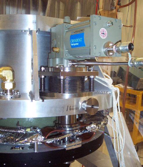 |
Top view of same Cold Head + vibration isolator atop the warm bulkhead. Below the warm bulkhead, the 1st stage copper straps and compression connector is seen. One of the LN2 loop internal bellows hoses is seen to the left of the cold head stage. |
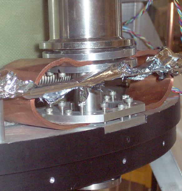 |
Detail view of cold head 1st stage copper strap system. The lower compression plate screws are only partially engaged in this assembly picture. Mylar multi-layer insulation (MLI) covers portions of a G10 thermal baffle seen cutting across the front of the copper strap system. |
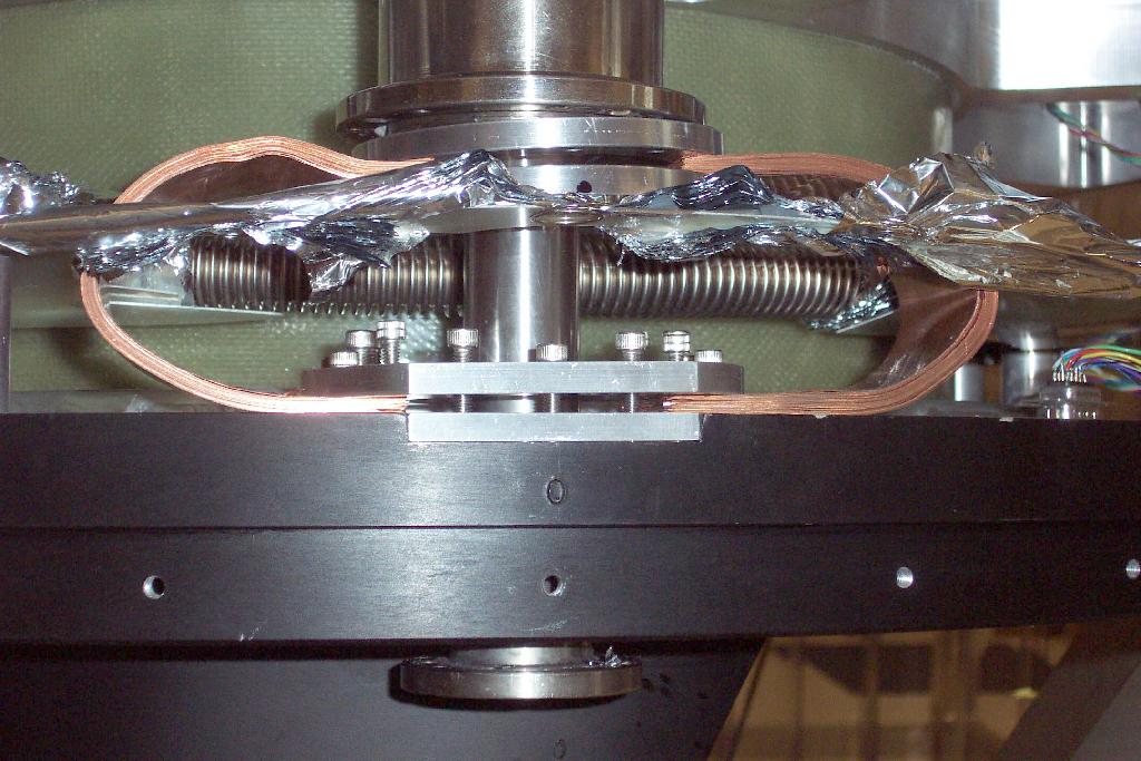 |
Another view of the 1st stage thermal strapping system. |
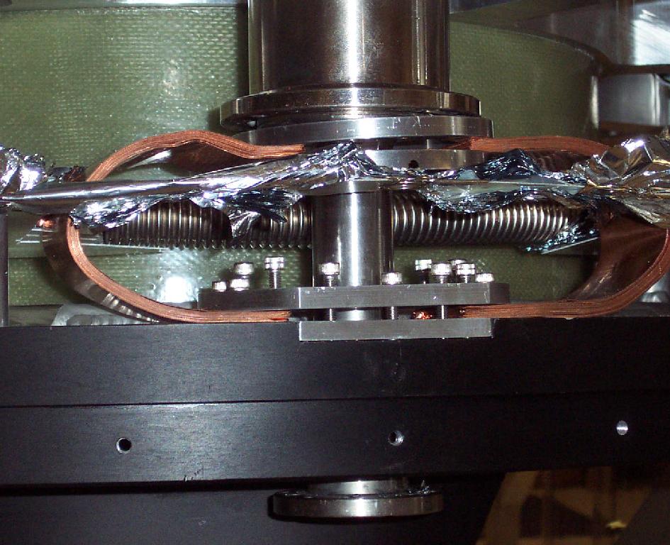 |
Side view of 1st stage thermal strapping, showing copper leaf plates |
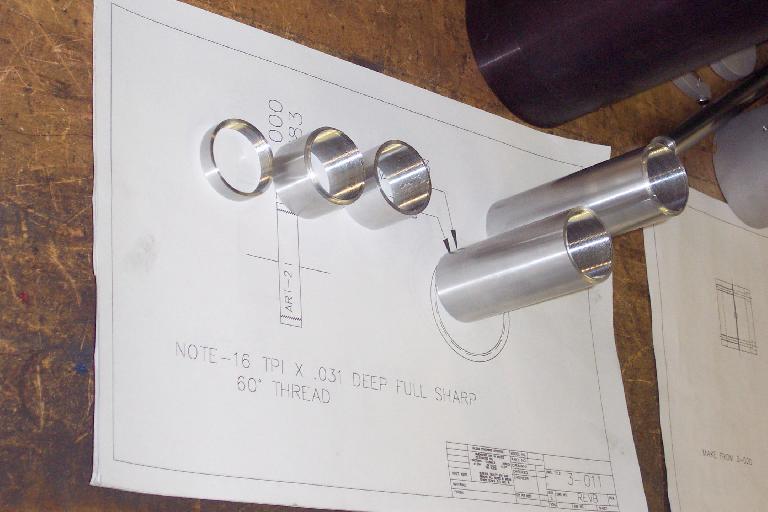 |
F/17 internal rifled baffles prior to bead blasting and anodizing. Scattered light is well-controlled by having the F/17 light within the camera block propagate only through these heavily internally ridged tubes. |
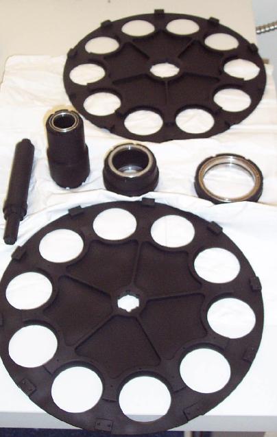 |
Filter Wheels after anodizing, with filter wheel hub components |
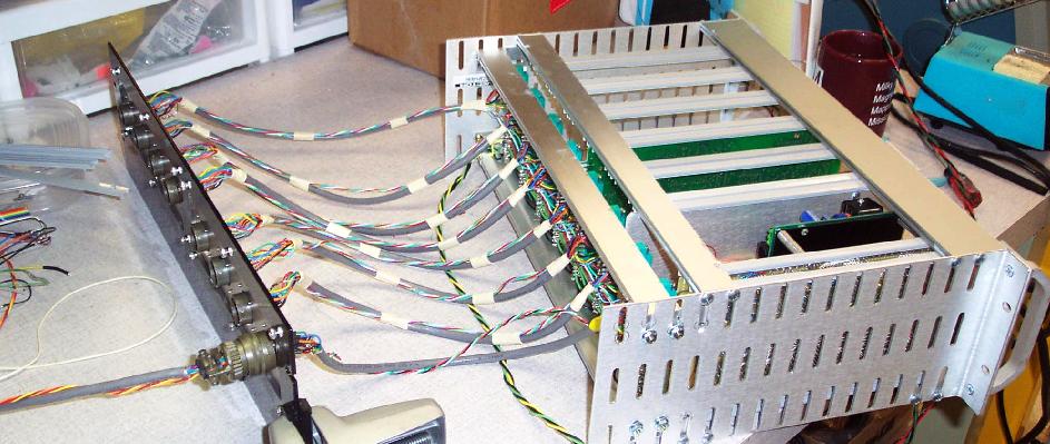 |
Motor control subrack with backplane connector plate |
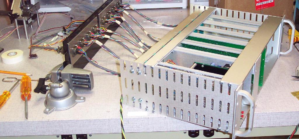 |
Bench configuration of motor control card, subrack, backplane, and stepper motor + sensor test unit. |