 |
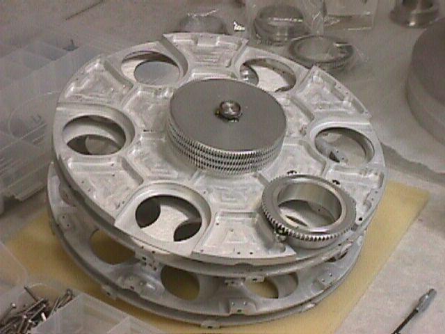
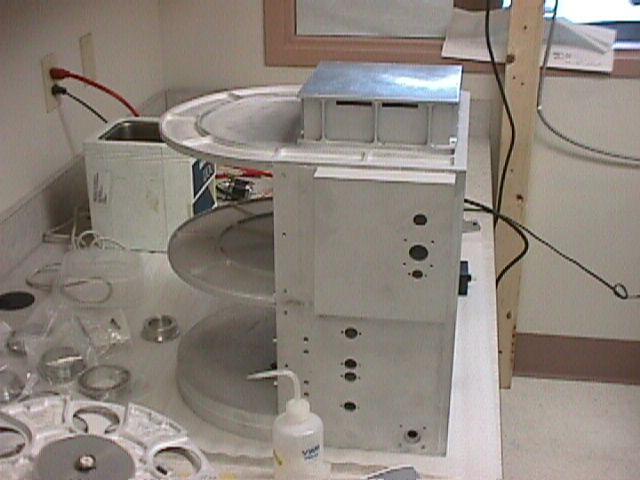
Filter Wheel stack on bench. Note geared HWP cell in place |
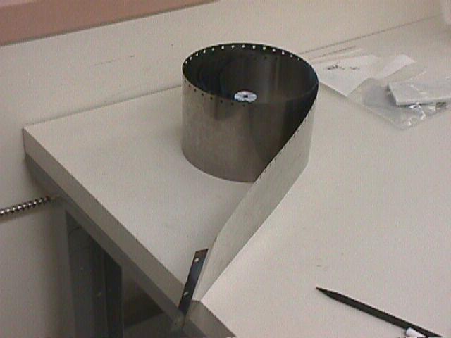 |
Test slit belt. Steel belt of thickness 0.003" with laser cut holes on one edge to engage the cog drive. |
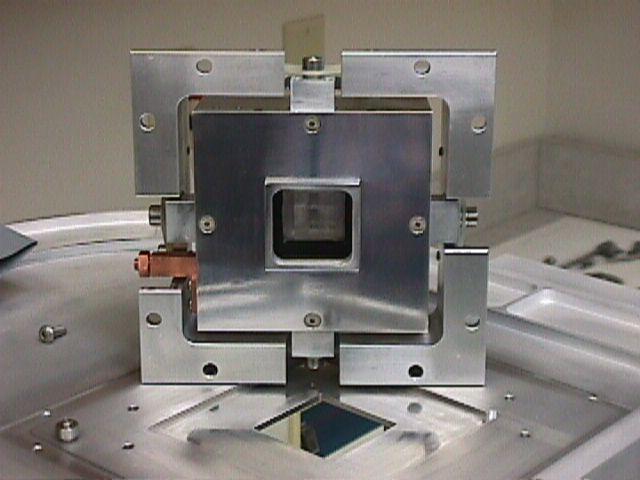 |
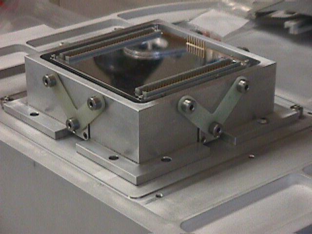
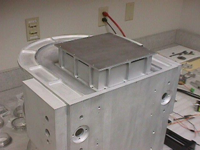
Detector Mount, resting atop back of filter box. The detector mount consists of the central polished aluminum block containing the detector socket and fanout board - this unit was manufactured by MKIR in Hawaii. Surrounding it is the detector mount "cage" or bracket. The detector block is cooled to 34K through the copper post seen at left. The cage is bolted to the back of the filter box and so is at 70K. The block and cage are connected via four G10 "V-tabs" that provide good thermal insulation and precise location of the detector relative to the optical beam. The block and the inner part of the cage are highly polished to reduce radiative thermal coupling between them. |
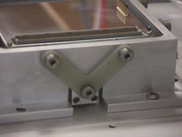 |
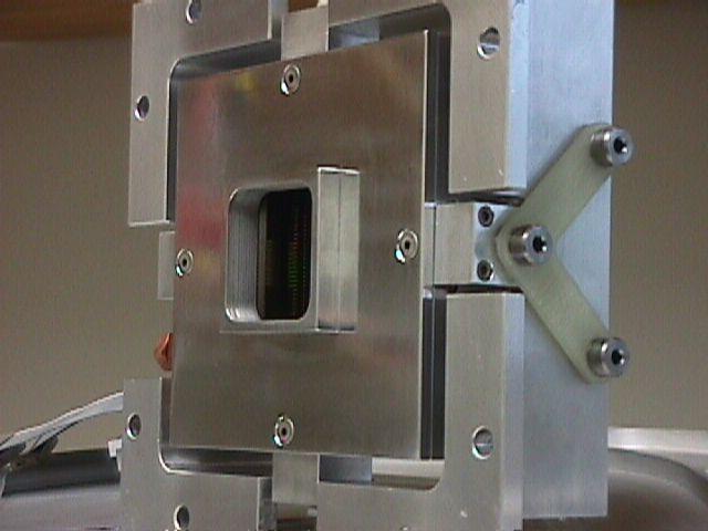
Side view of detector cage and block showing one of the four G10 V-tabs that connect between them. Also seen on the back of the detector mount block are one of the two VME connectors carrying the detector signals and the 8x1 IDC pin connector to the temperature sensor and resistive heaters used to create closed loop temperature control of the detector. |
 |
Oblique view of detector block, cage, and G10 V-tab. Note the short "snout" on the front of the detector block. This piece was fabricated in the BU SIF and contains find rulings inside the snout to act as a corregated light baffle. The snout protrudes into the filter box camera bay, and stops only some 0.020-0.032" from the camera block. |
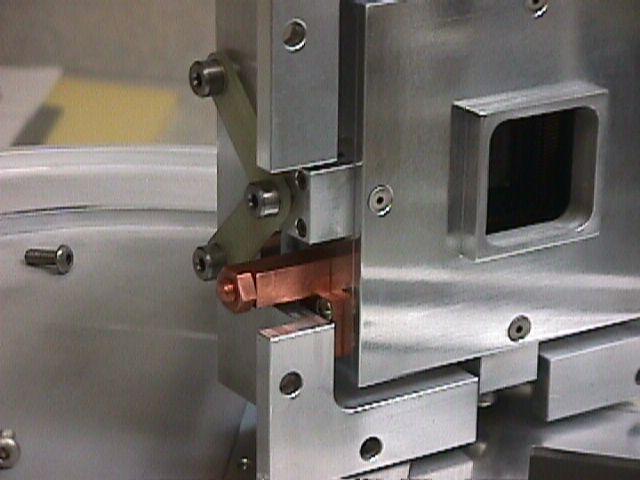 |
Oblique view showing the cold strap copper post. This is the thermal connection that goes to the second stage of the CTI refrigerator to cool the detector block to the 34 K needed for optimal operation. |
 |
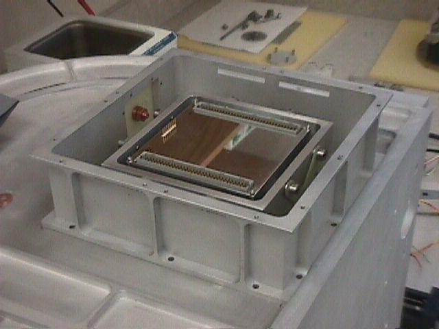
Back view of detector block and cage, on the back of the filter box. The cage is located precisely by three shoulder bearing collars on pins in the back of the filter box. One shoulder bearing is at center right, a second is at center left. |
 |
Surrounding the detector block and cage is the cover, consisting of the four-sided collar shown here and the flat cover that seals the top opening. This box is light-tight, but passes the cold strap to the detector (copper feed through just up and left of center) as well as the detector signals (through epoxied IDC connectors -- not yet installed in this picture). |
 |
Cover plate on detector unit box, mounted on back of filter box. On the bottom of the filter box, there are the openings and tapped holes that will accept the hardened steel insert pieces that form half of the kinematic mounts for the filter box and collimator. |
 |
Side view of detector box on back of filter box. |