 |
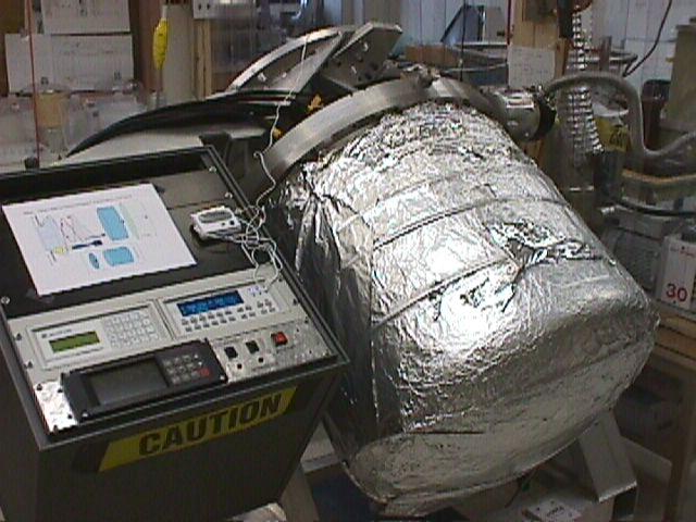
Mimir after second cold test. No broken bones... |
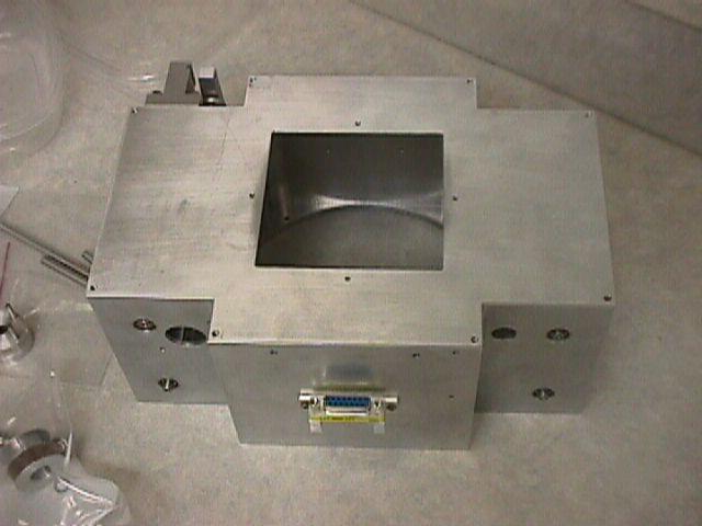 |
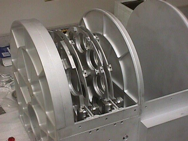
Slit belt unit outer box. This unit was to hold a long steel belt onto which specific "scenes" were to be photo- or laser-etched. The scenes would be the different spectroscopic slits and the picket fence needed for Wollaston prism polarimetry. The belt wrapped up on cogged rollers to the left and right and a stepper motor drove the belt back and forth to select the proper scene. The square opening at top is about 3.6x3.6 inches and is the physical size of the 10x10 arcmin field of view at the focal plane of the telescope, located within the Mimir cold volume. |
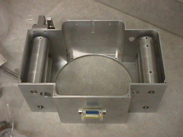 |
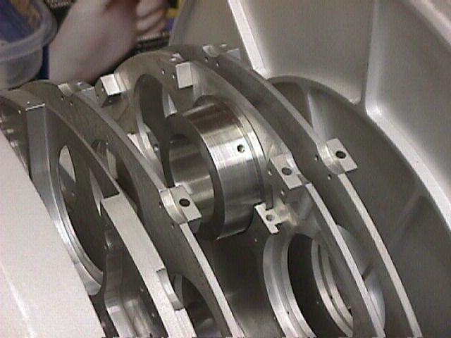
Cover removed from slit belt unit to reveal the cogged drive rollers (top) and the belt take-up rollers (underneath). Round opening at bottom fits over collimator unit, with the first two collimator lenses located within the volume of this slit belt unit. |
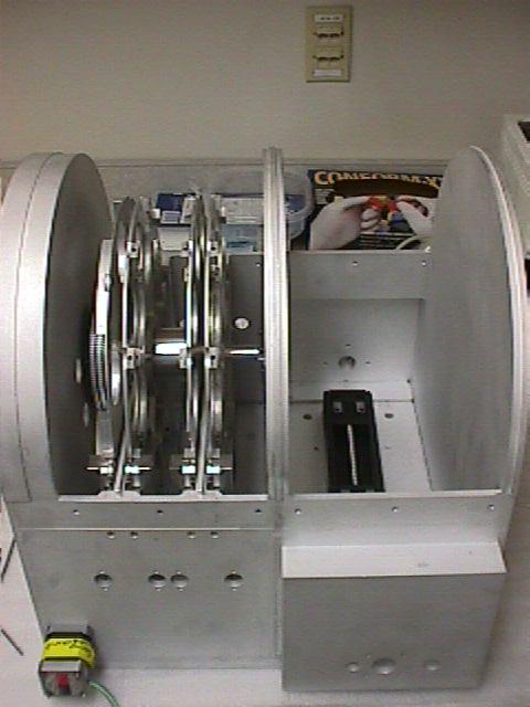 |
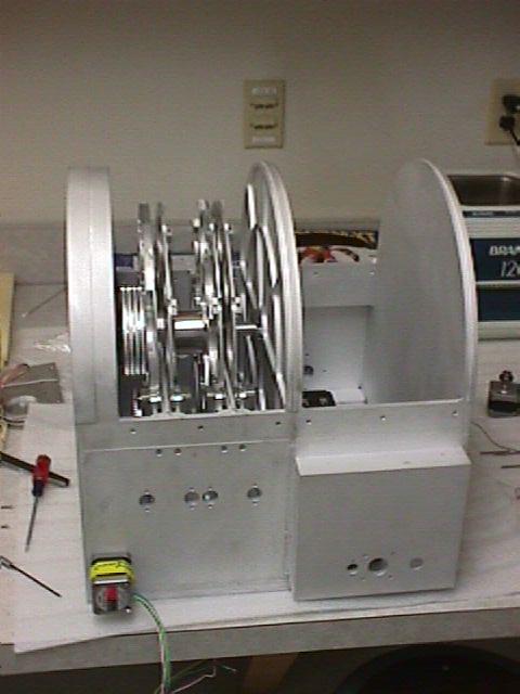
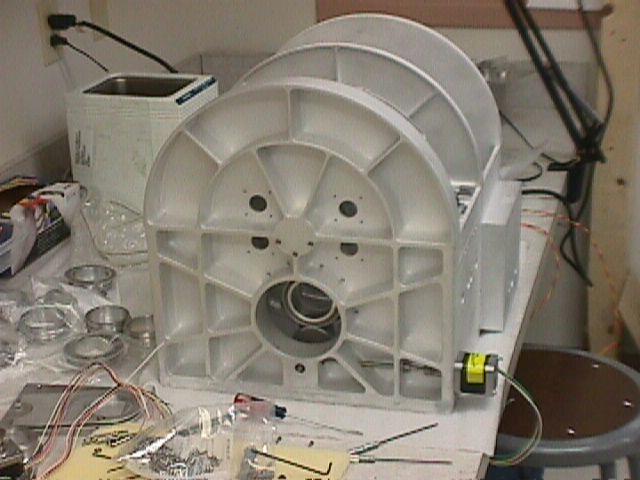
Filter box with four filter wheels installed in filter bay and THK screw-drive rail system (black) at bottom of camera bay. The polarimeter half-wave-plate drive stepper motor is located at lower left |
 |
Oblique view showing the four filter wheels, grouped as two wheels bracketing each of two internal bulkheads, used to control stray light. |
 |
Detail showing one filter cell blank located in a filter cell slot in the third wheel (FW2). |
 |
Side view of filter box showing four filter wheels, their nested common hub, and the four drive gears used to rotate each wheel (seen at left, between leftmost bulkhead of filter box and the first filter wheel). Circular holes on side of filter box into filter bay are to hold the sensors that register the fall of the detent arm with each filter position to indicate a wheel has a valid filter positioned in the optical beam. |
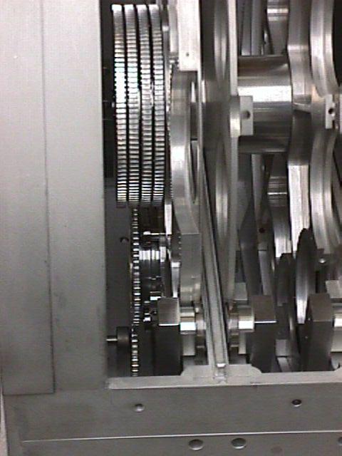 |
Top view inside filter bay. The four wheel gears are at center left. Below them are a HWP cell with outer gear meshed to the HWP drive gear. |
 |
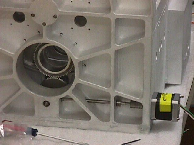
Front view showing HWP drive stepper motor (lower right), drive shaft, and HWP drive gear meshed with geared HWP cell (center of optical beam path). |
 |
Zoom showing HWP drive system in more detail. Bearing races can be seen at the vertical bulkhead holding the motor shaft and in the flat bulkhead below the optical axis, holding the right angle gear drive and the final gear engaged with the geared HWP cell in the first filter wheel. |
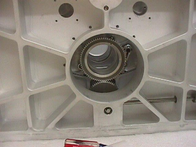 |
Further zoom of geared HWP cell and drive gear. The HWP cell is held in place by two fixed shoulder bearing races (at approximately 1-o'clock and 8-o'clock) and one shoulder bearing race on a flex pivoted arm (bearing race at 4-o'clock, flex pivot at 2-o'clock). The pivot arm allows the cell to be removed. The bearing races allow the cell to rotate. The races have a cylindrical shape, with flat sides, that engages a rectangular groove in the cell, locating the cell and controlling tilt or tip actions. |