 |
Dual shaft stepper motor with electromechanical brake (clutch plate and rotor at right). Assembled, this system is used to position the camera block, through the THK screw rail, and lock it in place. |
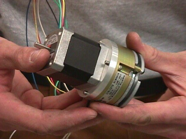 |
Motor and brake/clutch system assembled. |
 |
Closing up Mimir cryostat for second cooldown. Note temperature units and vacuum unit mounted in electronics rack. The cold shield / light cover that surrounds the cold space inside the cryostat has been attached to the cold bulkhead. A temperature sensing diode is attached to the back of the cold shield to measure temperature gradients along the cold shield from the cold bulkhead. |
 |
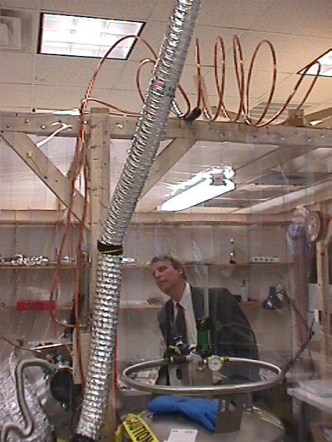
Front view of cryostat being closed up for the second cold test. Just beyond the cold shield, the green G10 shell supporting the 120 layers of MLI inside the cryostat shell can be seen. This G10 shell rests on the cold shield and against the warm bulkhead, forming a thermal barrier to warm IR radiation from the cryostat shell. |
 |
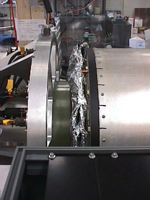
Side view of front, showing temperature sensor cabling. Also note that the LN2 precool loop stainless steel baffle hoses have been MLI wrapped to reduce LN2 boiling before entry to the cold bulkhead. |
 |
A new, thin G10 layer surrounds the central G10 collar and many layers of MLI have been attached to the new G10 layer to act as a radiation shield to prevent warm IR photons from the backside of the warm bulkhead from hitting the cold bulkhead. |
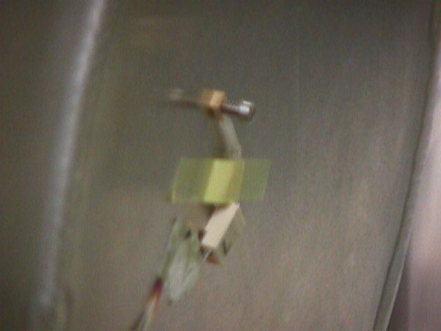 |
Zoom detail of temperature sensor placement on back of cold shield. |
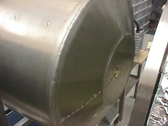 |
Unzoomed view of same placement. |
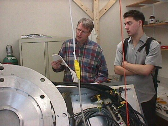 |
Eric Tollestrup and Kris Makrides puzzling over one of the electronics unit manuals. |
 |
Eric Tollestrup reading N2 flowmeter during cooldown |
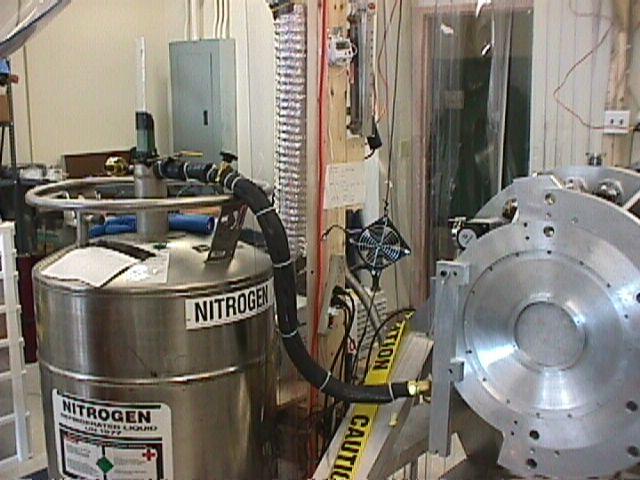 |
LN2 storage dewar connected to Mimir LN2 inlet. Notice the much shortened line and the increased thickness of insulation applied. |
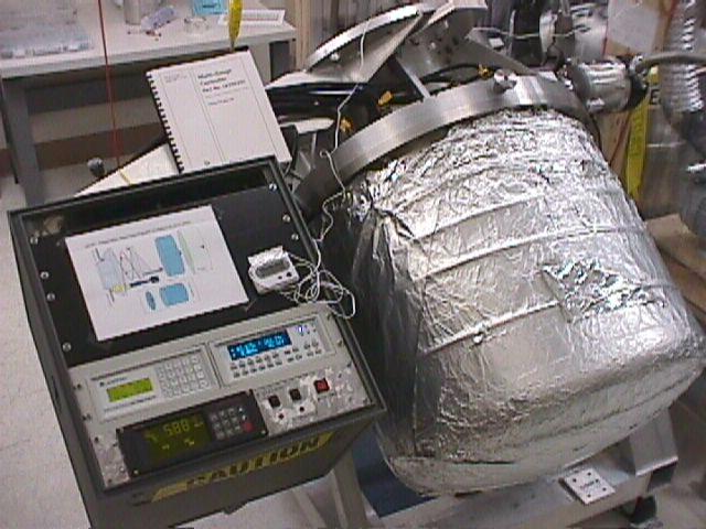 |
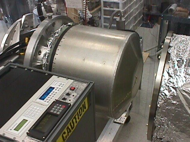
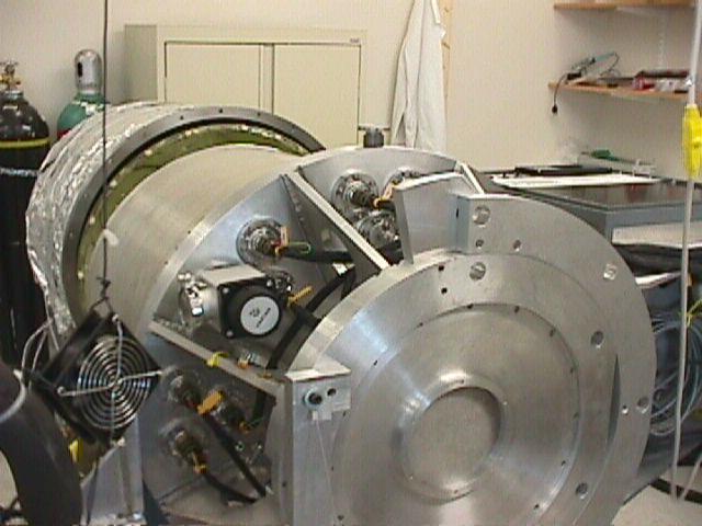
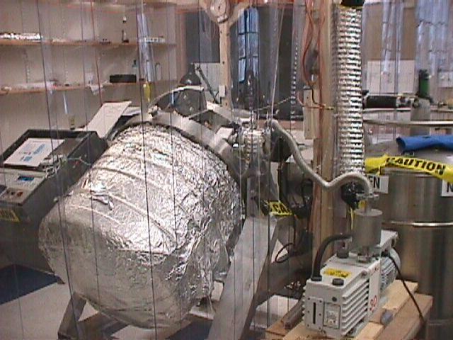
Mimir configuration during the second cold test. Electronics units in electronics rack, new sensor location cartoon above them. Cryostat shell still wrapped in heater tape and surrounded by aluminum foil. |
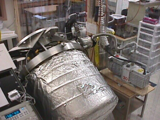 |
Top detail showing turbo pump connected to mech (oil) pump located outside the clean room. |
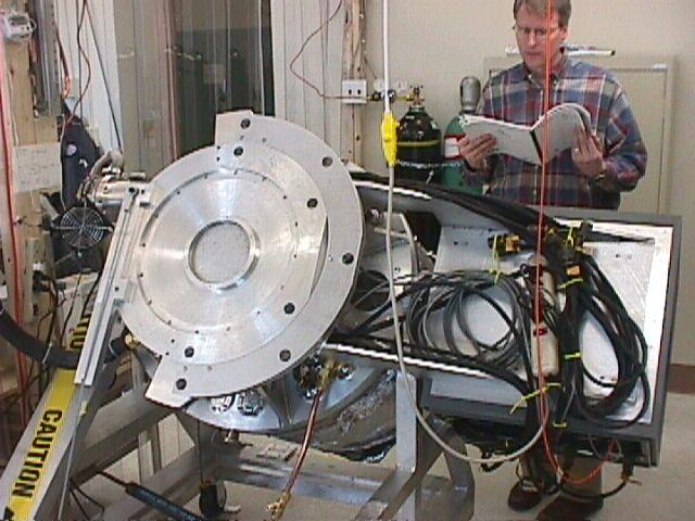 |
Eric Tollestrup continuing to read manuals as Mimir cools. |
 |
Side view from outside clean room during cooldown. |
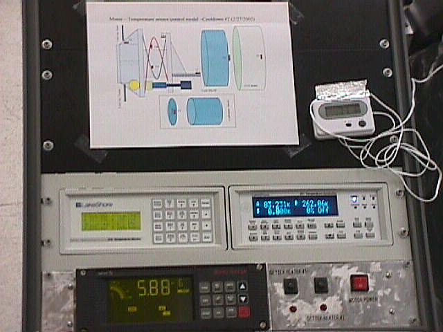 |
Sensors during cooldown. Vacuum gauge reads about 6x10^-6 torr. A sensor of temperature controller (at right) shows 83K at the LN2 inlet and 262K at the outlet. |
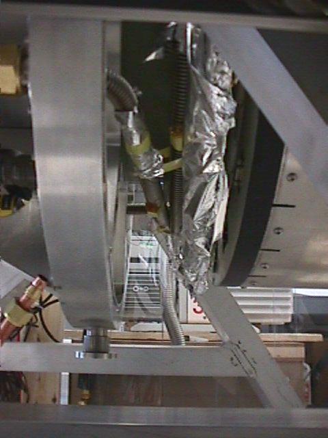 |
Detail showing temperature sensors locations on LN2 baffled hose inside cryostat. |