 |
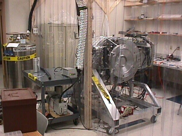
Lab configuration for first cold test. The Mimir cryostat and stand reside within the "biodome", our homemade clean room. It consisted of a fully enclosed space with filtered positive pressure ventilation and overlapping plastic curtain pieces in front. The LN2 storage dewar is at left, vacuum pumping system at lower center. |
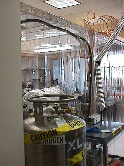 |
View of lab from lab entrance door. The copper piping loops atop the biodome/cleanroom are where the N2 exit gas is warmed back to room temperature before being introduced into the flow gauges. Cryostat shell has heater tape surrounded by aluminum foil. Black tubing across top front of clean room is the insulating jacket surrounding the copper pipe that connects the LN2 storage dewar to Mimir's LN2 loop inlet. During this cooldown, we quickly discovered that this LN2 piping system was very inefficient at delivering LN2 to Mimir. The pipe was shortened to about 1 meter and the insulation tripled and MLI wrapped to reduce heat intake and LN2 boiling prior to intake by Mimir. |
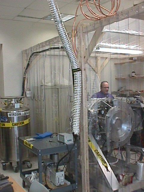 |
Domenic Sarcia inspecting temperature sensor readings during cooldown. |
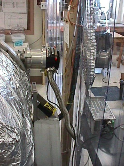 |
Turbo vacuum pump mounted on side of Mimir (actually mounted directly to valve). |
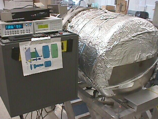 |
Rear view of cryostat and sensor readouts during cooldown. Cartoon taped to electronics box shows the internal locations of the various temperature sensors. |
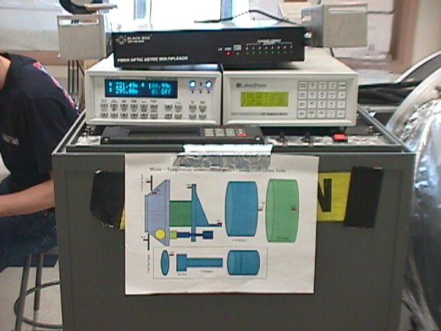 |
Closer view of sensor location cartoon. Atop it, at left is the LakeShore LS331 temperature controller and at right is the LS218 temperature monitor. Fiber multiplexer is at top. |
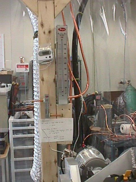 |
N2 flow gauge during cooldown. Note that the indicating ball is in the lowest range of the flow meter. |
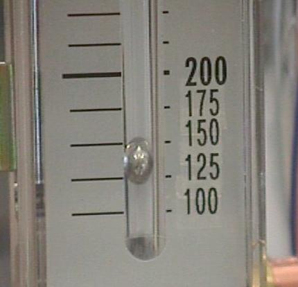 |
Zoomed view of flow meter during cooldown, showing a flow rate of about 135 standard cubic feet per hour (SCFH). |
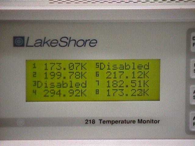 |
LS218 temperature monitor readout during cooldown. |
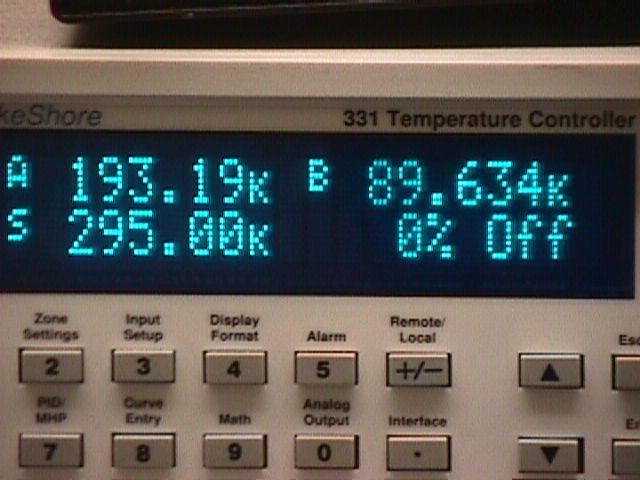 |
LS331 temperature controller during cooldown. Sensor B and A report the temperatures of the LN2 precool loop inlet and outlet, respectively. |
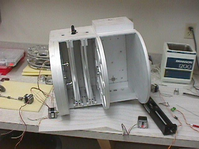 |
Filter Box with motors on bench. Note THK screw drive unit at right (to be installed as the camera drive unit) and filter wheel stack at upper left behind filter box. |
 |
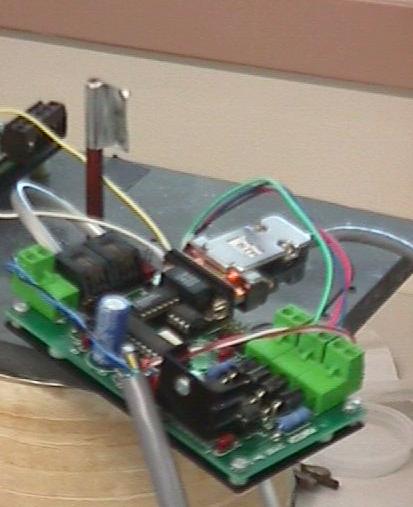
Setup for testing stepper motors in liquid nitrogen. Dewar with LN2 at center, stepper motor controller atop. Power supply at left, computer for commanding stepper controller at right. |
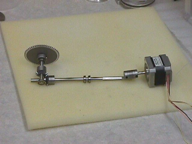 |
Gear drive system for half-wave-plate rotation, consisting of a stepper motor with flex coupling, drive shaft with twin bearing races, right angle gear drive, second shaft with twin bearing races, and HWP filter cell drive gear. This system is installed inside the filter box below the filter wheel stack. |
 |
Test stand and stepper controller for LN2 plunge testing of stepper motors. The aluminum can is a short dewar filled with LN2. Inside, the motor being tested is mounted on G10 standoffs. The motor shaft is attached to a longer G10 shaft that exits through the center of the gray plate. The motor's operation and stalling force can be seen and probed using the extension shaft. |
 |
The rotatinng aluminum "flag" attached to the brown shaft provides direct visual verification that the stepper motor is working while surrounded by LN2. |