 |
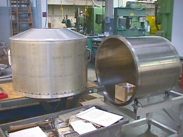
Cold shield (at left) and stainless steel cryostat cover (at right)
in BU SIF. |
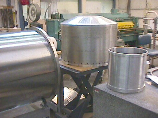 |
Another view showing cold shield, cryostat cover, and front cold
cylinder. |
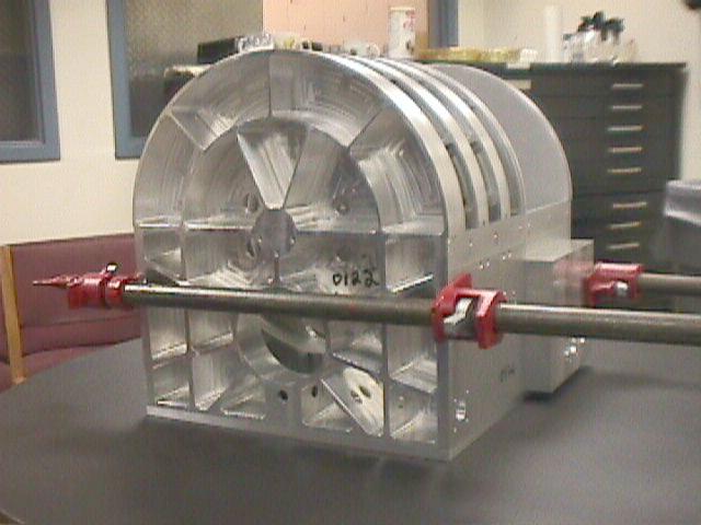 |
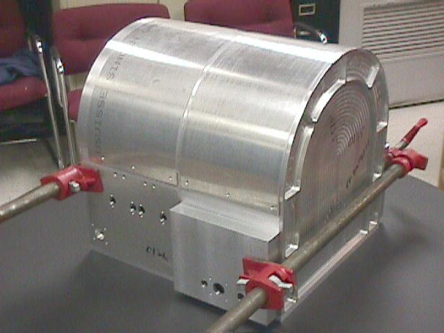
Filter Box, assembled and held by clamps, before being sent off
for dip brazing. |
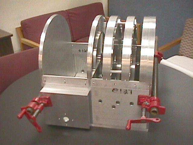 |
Side view of filter box, with top covers removed. Before dip brazing.
All parts were manufactured by the BU SIF. |
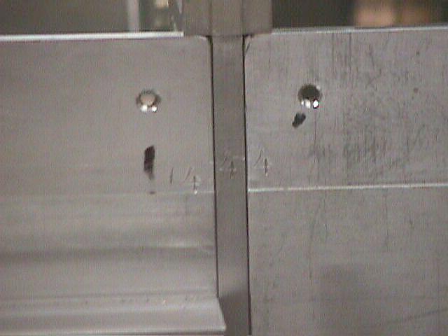 |
Detail showing alignment marks ("4"s) to guide dip brazing
for one portion of the filter box |
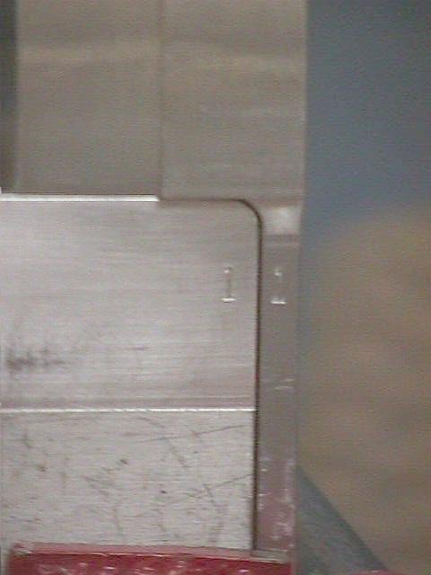 |
Detail of front end of filter box, with alignment marks ("1"s)
to guide dip brazing |
 |
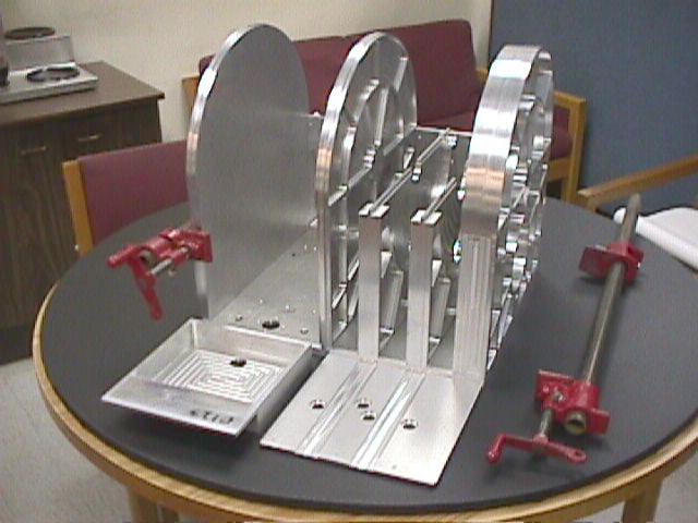
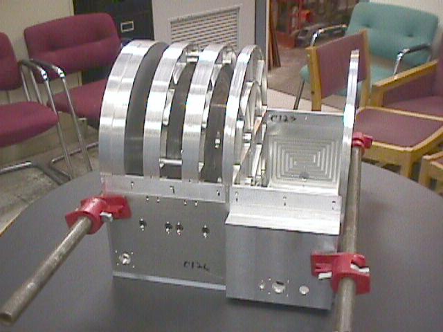
Filter box, prior to brazing, with top covers in place. The entire
base (absent the top covers) would be dipped into molten sodium to
braze its individual parts into one, coherent whole box. |
 |
Back view of filter box prior to dip brazing. This back side is
where the detector box will eventually be attached. |
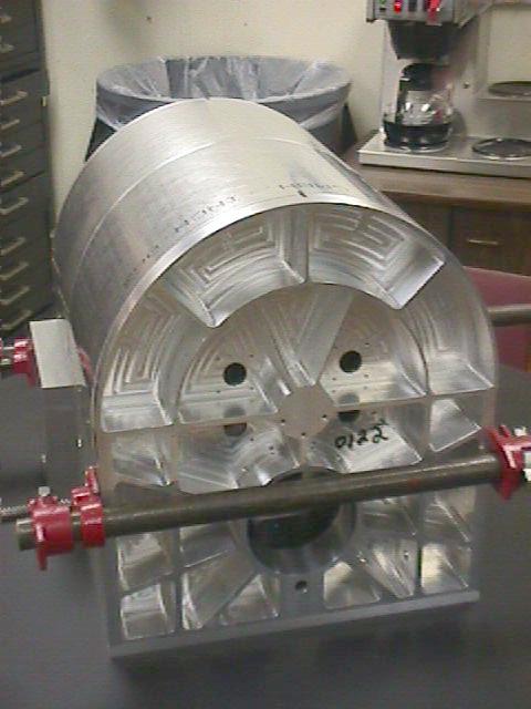 |
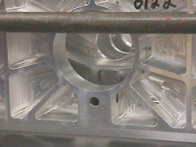
Front view of filter box, prior to brazing. The large hole below
the front clamp will eventually accept and hold the collimator. The
four smaller holes above it are for the four filter wheel stepper
motor shafts to pass into the central volume. Notice the deep light
weighting cutouts in this front cover, used to provide stiffness while
reducing cold mass to a minimum. |
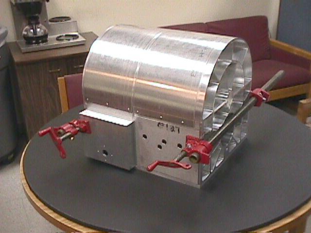 |
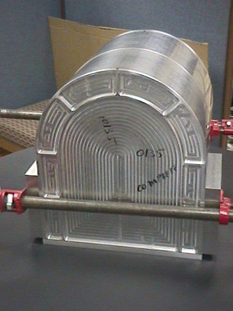
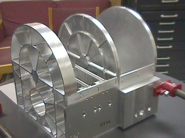
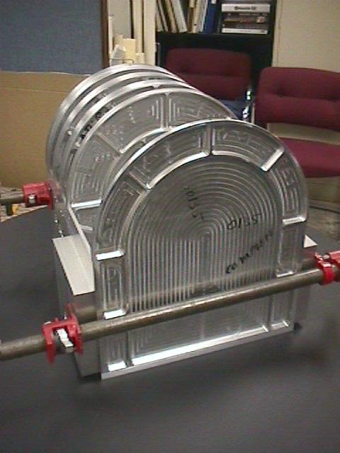
Side view of filter box prior to brazing. Also called the cathedral,
for somewhat obvious reasons... |
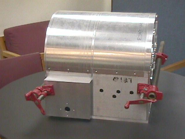 |
Side view, showing penetrations at right for the electrical connectors
carrying signals to/from the filter wheel encoders, and at lower left
for the serpentine cover to allow gas to escape the filter box when
vacuum pumping. |
 |
Detail view of front of filter box showing high degree of passive
baffling of light path through the several internal bulkheads of the
filter box. |
 |
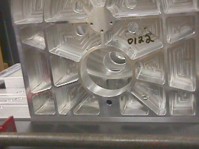
Closer detail showing the penetrations below the optical opening
for the bearing race and drive shaft of the half-wave plate rotation
system. The forward hole hosts a shaft for the right-angle gear driven
from the shaft entering from the left through the three internal bulkheads. |
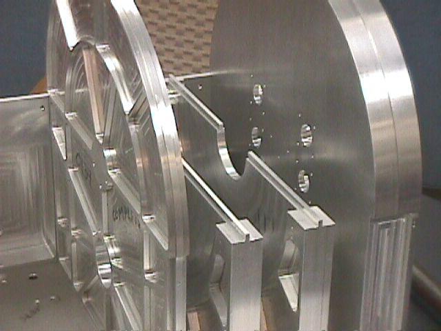 |
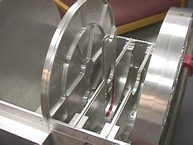
Internal view of filter box, with one side removed, prior to brazing.
At right is the front bulkhead. Next are the POL-FW1 bulkhead, the
FW2-FW3 bulkhead, and the filter-camera bulkhead that separates the
region containing the filter wheels from the region containing the
camera block. |
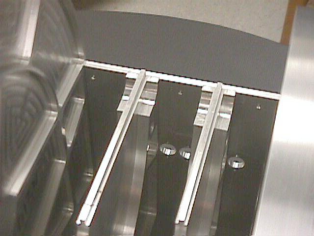 |
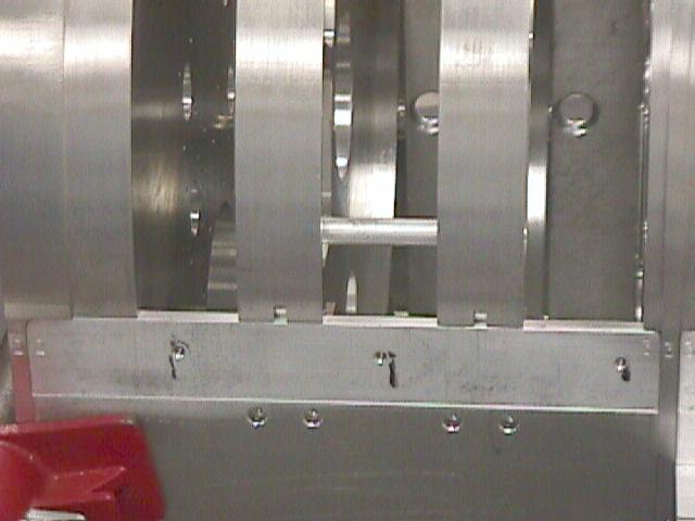
Internal view of filter wheel zone, showing the tongue portions
of the bulkheads that will mate to the grooves in the top cover to
provide superb stray light control within Mimir. Also note that the
filter wheels are locates within pockets in the bulkheads, with only
about 0.032" clearance, to also control stray light. |
 |
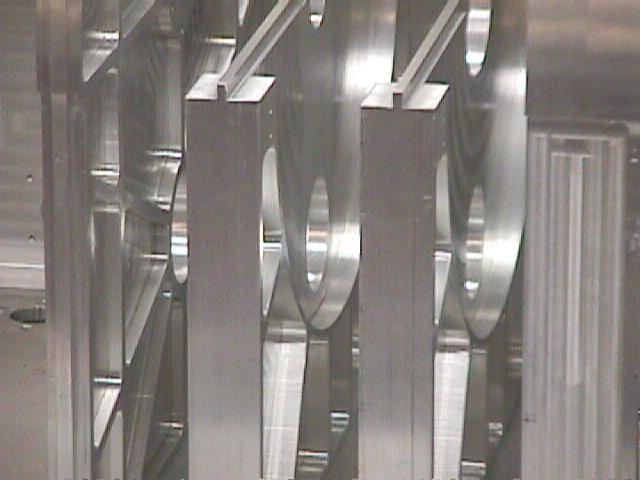
Filter Box, with side removed, prior to dip brazing, showing internal
filter box baffles and their light weighting. |
 |
Detail view showing removable pupil mask holder and its tongue and
groove slot in the FW2-FW3 bulkhead within the filter box. The initial
pupil mask was designed based on model telescope and instrument parameters.
After initial telescope operations, an improved pupil mask was designed
and inserted in this removable piece that fits snugly into the bulkhead. |
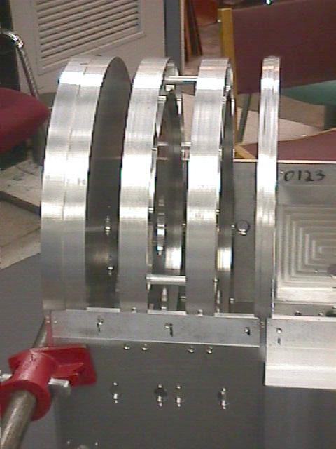 |
Filter box, showing bulkhead tops, absent the half-cylindrical cover,
prior to brazing |
 |
Filter box, prior to brazing, with covers and bulkhead tops removed.
Holes on this side accomodate the detent sensor adjustments (four
left hole patterns), and the motor/brake and sensor system for the
camera box drive (lower right). |
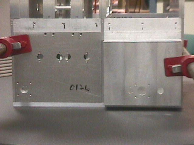 |
Side detail. Lower left hole pattern is for the HWP drive stepper
motor. Central four hole patterns for the filter wheel detent sensor
bias magnet adjustments. Lower right hole patterns are for the sensor
and stepper motor for the camera block drive system. Rightmost lower
hole is for the electrical connector for the internal reed limit switches
for the camera block drive system. |
 |
Oblique view highlighting the camera block bay situated aft of the
filter wheel bay. Note the pushed out covers (front and rear in this
photo) in the filter bay. These were needed to accomodate the range
of motion and size of the camera block. |
 |
Detail showing filter box, with bulkhead tops installed. |
 |
Oblique back view of filter box prior to brazing. The back bulkhead
will be machined after brazing to accomodate the detector package. |
 |
Side view detail, showing tight filter wheel clearance zones, tongue
to mate to cover top groove, and passive baffling of optical path
within Mimir. |