 |
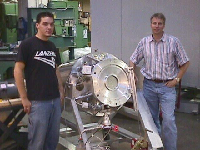
Undergraduate Kris Makrides (left) and Dr. Eric Tollestrup (right)
flank the Mimir cryostat in preparation for the resumed leak testing
in the BU SIF. |
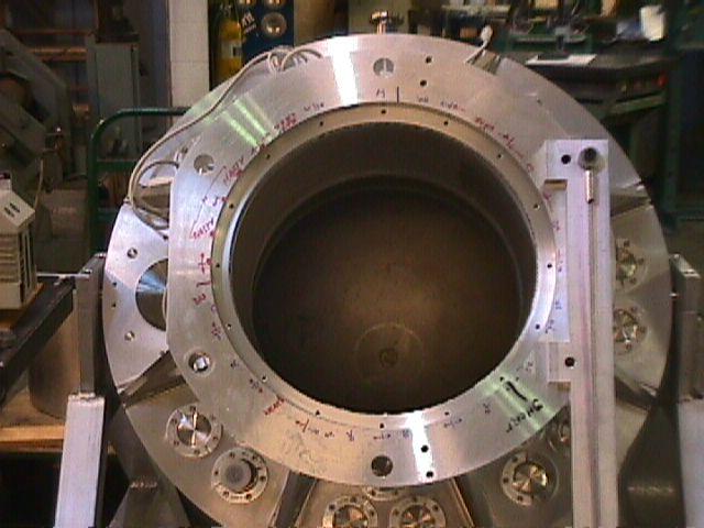 |
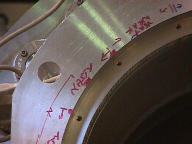
Preparation for second leak test. Red and black marks on front of
telescope flange indicate which front cover screw holes are long and
which are short. Zones marked by red line (e.g., 10 o'clock zone)
indicate where leak checker found gross leaks. |
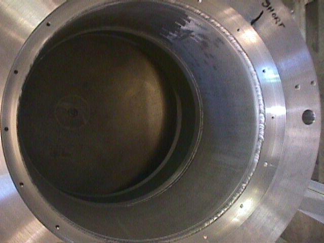 |
Cryostat interior, showing internal weld of telescope flange to
warm cylinder connecting flange to Big Ben's large bulkhead. Just
forward of the weld is a thin lip that accepts the front cover attachment
screws. This lip's ID was too small, causing interference with the
front cover (see below) and was the cause of the gross leak. |
 |
A poor picture of the front cover, in particular the portion that
interferes with the interior lip shown in the picture above. To solve
the gross leak problem, this front cover was put back on the lathe
and the OD of this surface was turned down to allow the internal lip
of the front telescope flange to pass without interference. |
 |
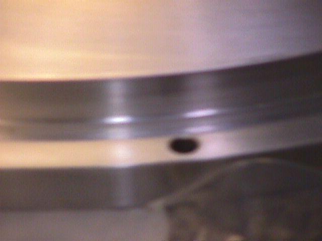
Zoom of interfering lip and external mark of where the gross leak
was found. |
 |
Gross leak fixed, pumping resumed. Turbo at bottom. |
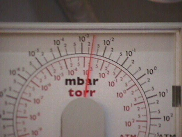 |
Vacuum gauge, showing pressure between 10^-2 and 10^-3 torr. |
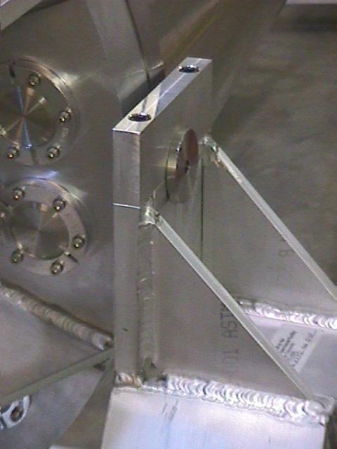 |
Detail showing clovis pin and split block to capture it, supporting
Mimir cryostat on instrument cart. |
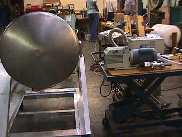 |
Tail end of stainless steel cryostat shell. This spun portion was
welded onto the rolled SS cylindrical shell to form the full SS cryostat
cover. |
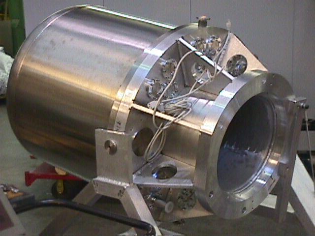 |
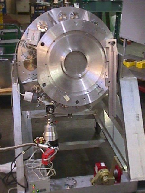
Mimir cryostat side view. From left: stainless steel cryostat cover,
warm bulkhead, gussetts and inner warm cylinder, telescope flange,
all on instrument cart. |
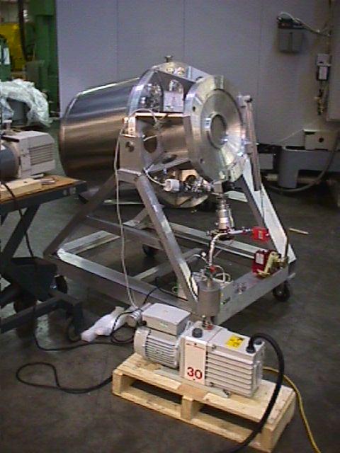 |
Mimir cryostat during leak testing, showing vacuum pump system (mech
+ turbo). |
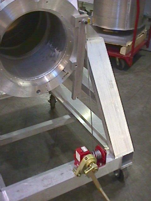 |
Detail showing winch system used to crank Mimir cryostat from vertical
to horizontal position. |