Mimir March Servicing Disassembly Checklist and Long Report
Present during part of all of servicing: Dan Clemens, Nina Bonaventura, Marc Buie
Checklist and inspection list:
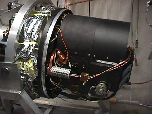
1. Assess State of Mimir in Clean Room
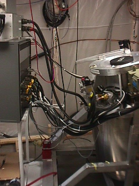
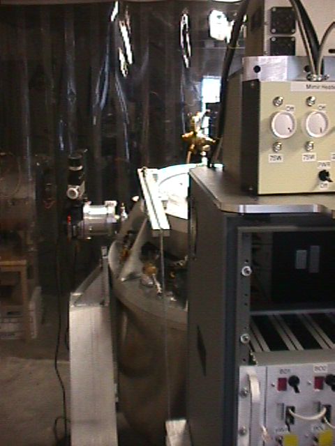
A. 20050306: Mimir cryostat connected to electronics box, Leach electronics, external heater control, dry N2 fill. Turbo still attached and under hard vacuum.
B. Cryostat at room temp and 1 torr N2
2. Mitigate anomalies or non-standard states
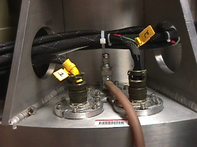
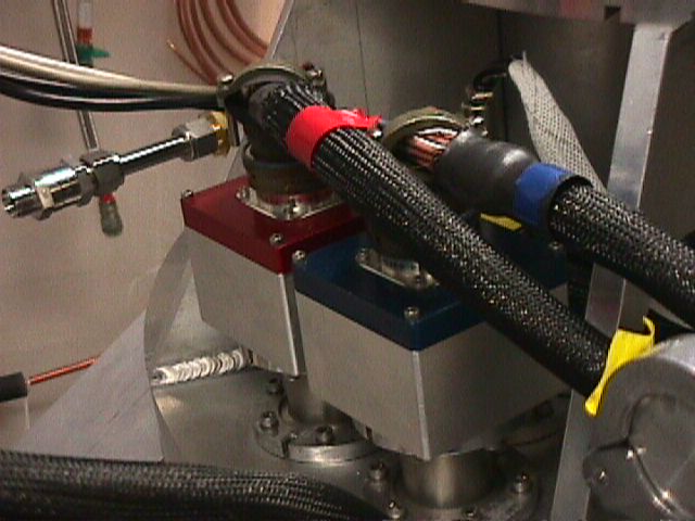
A. Detector: add shorting plugs
1. Attach static-preventing wrist straps and grounding wires to cryostat
a. Picture 7
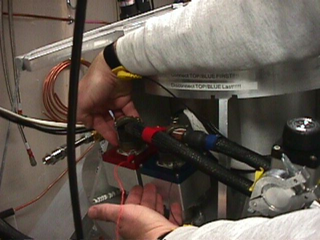
2. Remove Red Detector Connector
a. Picture 8
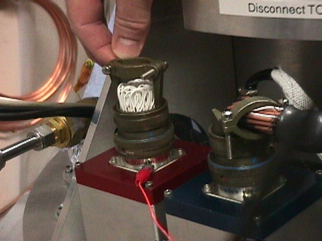
3. Install Shorting Plug to Red Receptacle
a. Picture 9
4. Remove Blue Detector Connector
5. Install Shorting Plug to Blue Receptacle
B. Leach Electronics: Turned off, removed
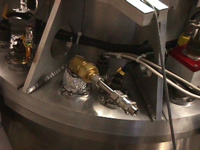
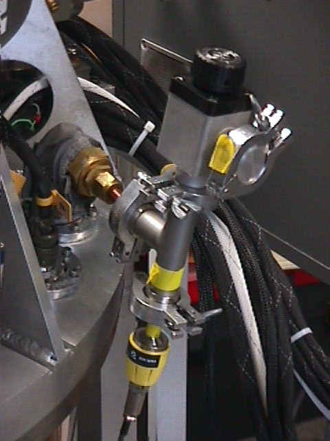
C. Remove External heater controller cable, plug
1. Picture 10
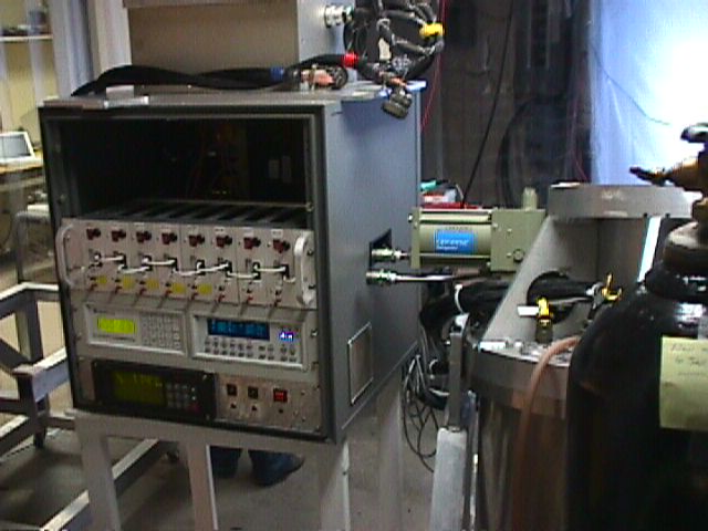
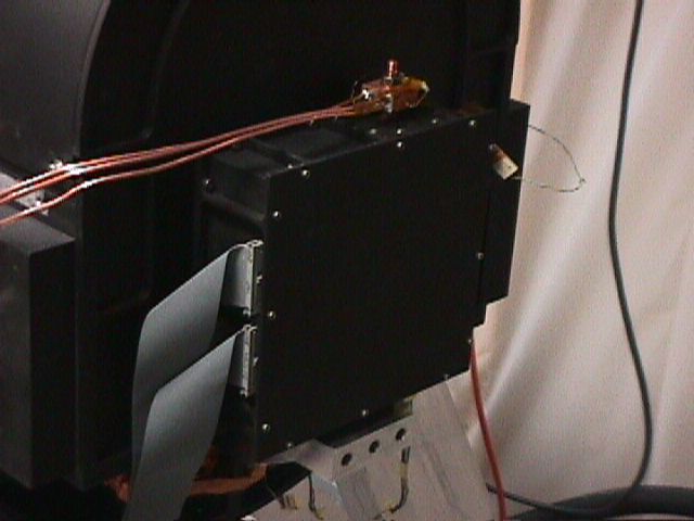
D. Electronics Box: Turned off, moved to side
1. Picture 11
E. Turbo: vent to cryostat
F. Cryostat Shell Cart: Reattach Shell Wheels
G.
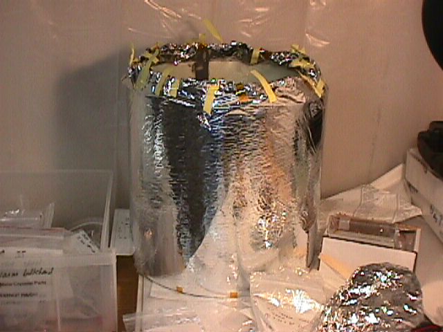
LN2
1. 20050306 -> it really smells of pump oil or something organic
a. we may need to clean it with solvent of some kind
b. we should only pump on it with a turbo or oil-less pump when on the telescope
2. Picture 14
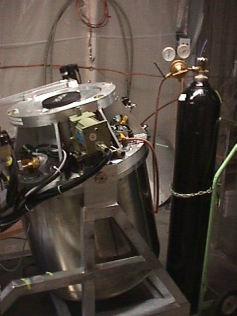
H. Vacuum: back fill with N2 to STP through needle valve on warm bulkhead
1. N2 pressure no more than 2-3 psi gauge (e.g., very low)
2. Slowly at first, more rapidly later – through needle valve, this takes ~1/2 hour
3. TC1 may not be calibrated after a long use, so take care not to overpressurize Mimir
a. This isn’t fatal, as the front window sits on an O-ring, pressurize by an outside spring. If the internal pressure exceeds outside, the window will pop off the O-ring (it will “burp”).
b. Alternatively, pinching the rubber hose from the N2 bottle to the needle valve can show whether Mimir is under- or over-pressurized. If pinching the hose causes the exit pressure gauge on the N2 bottle to *increase*, then Mimir is still underpressured. If the gauge on the N2 bottle, *decreases*, Mimir is overpressured.
I. Turbo: remove and cap openings. Put in a safe place.
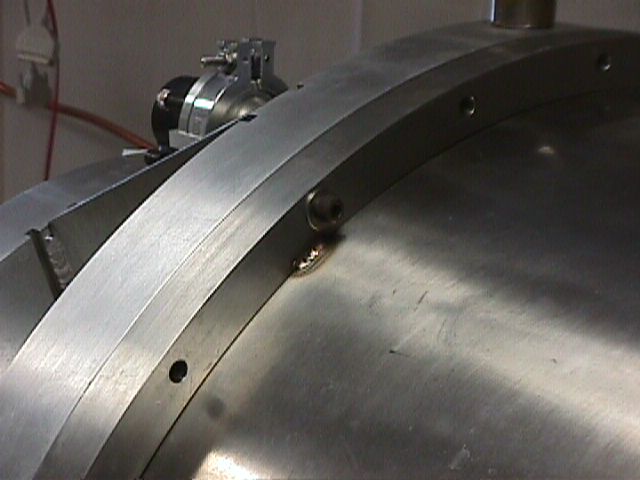
3. Prepare Cryostat for opening
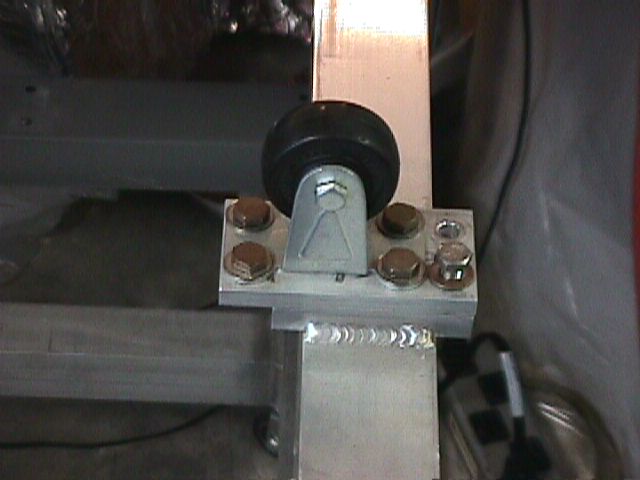
A. Inspect front cable winch, take-up wheel
B. Inspect front cable attachment and level arm
C. Reposition Mimir as needed within clean room for ease of access all around
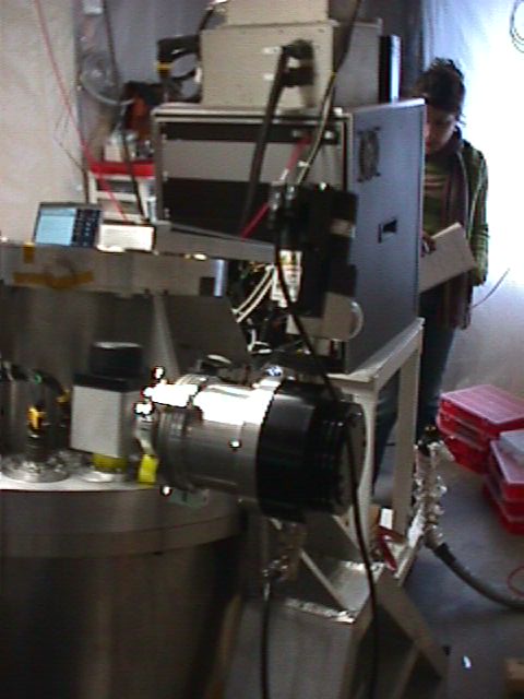
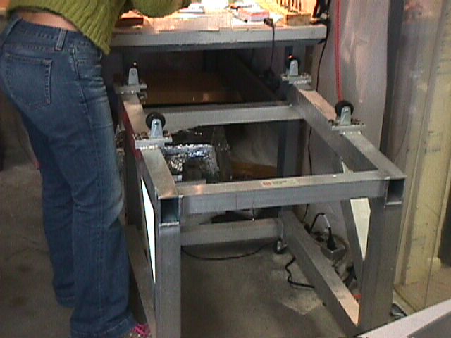
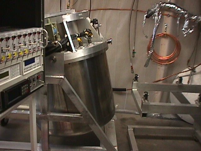
D. Crank Cryostat to horizontal position
1. Watch and guide cables
2. Picture 15
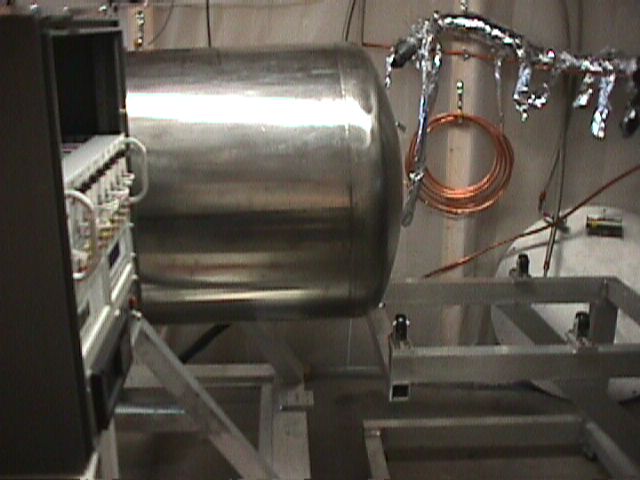
E. Guide Cryostat Shell Cart under cryostat into correct position
1. Picture 16
F. Reverse crank, slowly, to ease cryostat shell onto shell cart wheels
1. Note, the winch cable must remain taut – no slack permitted, as cryostat shell cannot support the full weight of Mimir in this position
4. Open Cryostat Outer Shell
A. Loosen and remove the bolts holding the SS shell front flange to the warm bulkhead
1. Picture 19
2. Put all screws and washers into bag marked “Mimir SS Cryostat Shell to warm bulkhead bolts”
3. Put bag into clear parts drawer marked “Mimir Cryostat Parts: DO NOT RAID!”
B. Slowly pull cryostat shell on cart back from warm bulkhead
1. Watch for hung wires, cables
2. Don’t scrape against internal cold shield
5. Cover Cryostat Shell with End Plate
A. Remove O-ring from Mimir warm bulkhead
B. Install O-ring on Cryostat Shell End Plate
C.
D. Tighten to engage O-ring, but do not overtighten
6. Prepare Cryostat Shell for vacuum pumping
A. Attach NW25 vacuum valve to NW40 tee to end cover using NW25 to NW40 transition piece
1. Picture 20
B. Attach multirange vacuum pressure gauge (MWG) to other end of NW40 tee (same picture)
C. Attach vacuum gauge electrical cable from controller to gauge
1. Picture 21
D. Turn on vacuum gauge controller
1. Needle should swing clockwise to nearly ATM
E. Calibrate vacuum gauge
1. On the back of the gauge head, locate the hole marked “ATM”
2. Insert end of small allen wrench and push inward
3. Needle on gauge controller should move to ATM value
4. Remove allen wrench
7. Vacuum pump cryostat shell
A. Attach suitable pumping station to cryostat shell
B. Open all valves
C. Start pumping station
D. Pump until shell pressure is under 10^-3 torr
E. Close off all vacuum valves
F. Turn off vacuum pumping station, but leave multirange vacuum gauge operating to monitor pressure.
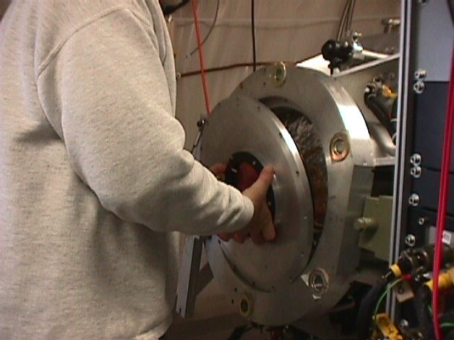
8. Remove Mimir Front Cover
A. Crank winch so Mimir rotates about 20 degrees away from horizontal, closer to vertical to put some layback into front cover unit (so it won’t fall easily onto the floor)
B. Remove any temperature sensor and wiring attached to front window.
C. Leave black “Mimir” cover over window while removing cover screws
D. Remove all cover screws, putting them into the bag marked “Mimir Front Cover (Window Cover) Screws”
1. Picture 22
E. Remove black “Mimir” cover
F. Holding front cover by front window mounting circle, lay cover back onto arms
1. Picture 23
G. Carefully transport cover to safe location, covering bottom with lens paper and foam
1. Keep O-ring with cover
H. Cover front window with black “Mimir” cover
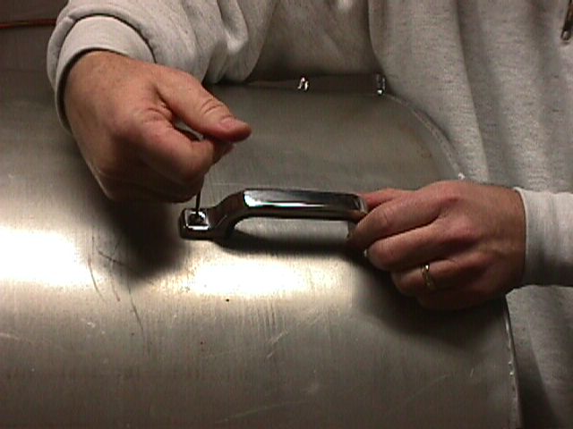
9. Remove Cold Shield
A. Attach handles to cold shield, using screws in the bag containing the handles
1. Picture 24
B. Remove the three large screws on the back of the cold shield
1. Picture 26
2. Put them in the bag marked “Mimir Rear Cold Shield Screws to Clemens Clamp”
C. Remove the 32 button head screws holding the front of the cold shield to the cold bulkhead
1. Picture 25
2. Put them in a bag marked “Cold Shield Button Head Screws”
a. Ideally, we use these screws once, then throw them away, but we need a supply to be able to do this
b. To reorder, the type is 3/8 x 10-32 Button Head SS, we use 32 per closing of Mimir
D. Carefully remove the cold shield (taking care not to scratch the filter box or other components) and store in a dust-free location.
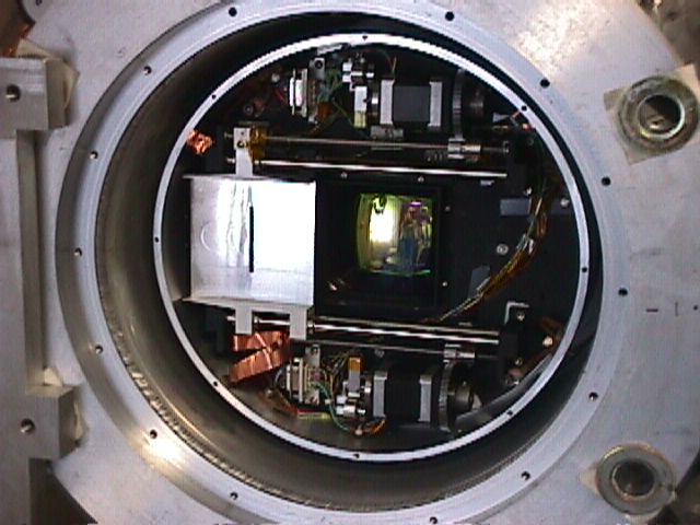
10. Pictures of Mimir guts after cold shield removal
11. Remove Detector Cage Back Cover
A. Picture 101
B. Save screws in bag marked “Detector Cover Plate Bolts”
1. 20050306: No obvious aluminum chips or shavings found. Also, I can’t see any chips inside near/under the detector block where so many were found in November. Conclude that it is unlikely there are chips on the detector and we should be able to forgo opening the detector package this time
12. Remove Outer MLI cover of front cold shield
A. Save in a safe location
1. Picture 102
B. Exposes MLI covering cold shield
1. Picture 103
13. Remove Inner MLI cover of front cold shield
A. Peel back yellow tape
B. Remove MLI pack from front of cold shield
C. Pull out MLI covered G10 cylindrical Shell
1. Picture 104
D. Pull out loose MLI front cover
E. Exposing Front Cold Shield Cover
1. Picture 105
14. Remove Front Cold Shield Front Cover
A. Save screws in bag marked “Mimir Front Cold Shield Cover Screws”
B. Exposing Decker Guts
1. Picture 106
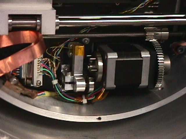
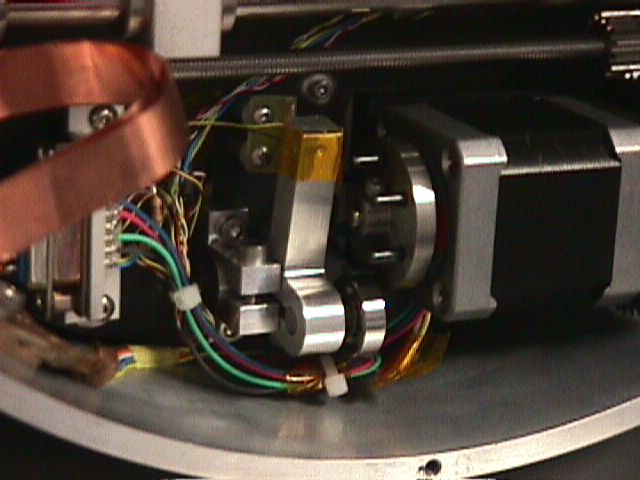
15. Inspection of Decker
A. 20050306:
1. No broken parts.
2. No evidence of aluminum chips or dust.
3. The cold strap to the slit plate is located non-optimally (might present some interference)
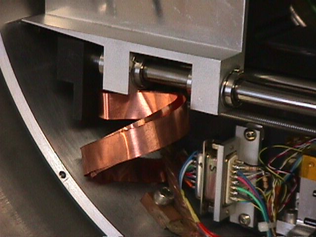
b. DC recommends removal of the cold strap entirely
4. The cold strap to the decker was decommissioned in November. It is still in the unit and presents some interference. DC recommends removal
a. Picture 109
5. Pictures of Decker parts
a. Picture 110 – Motor drive, detent detail
b. Picture 112 – zoom of detent arm raised on drive pin
16. Remove Filter Box Covers
A. Remove screws holding camera zone cover in place
1. Picture 113
2. Save in bag marked “Mimir Filter Box Cover Screws”
B. Inspect camera zone
1. 20050306: No evidence of aluminum chip or scoring of back bulhead
C. Remove screws holding filter zone cover in place
1. Save in same bag as above
D. Inspect filter zone
1. Picture 114
2. 20050306: looks quite good. Some aluminum dust, about what I would have expected.
17. 20050306 – DC+MB evaluated detector zone and camera zone and declared them fine, so reinstalled their covers
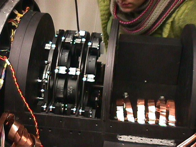
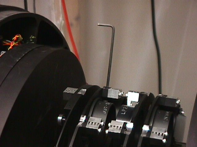
18. Removing Filters preparatory for Filter Wheel removal
A. With proper allen wrench, back off filter capture blocks 3 full turns of each screw
1. Picture 115
B. Remove filter cell, wrap in lens paper, put away in safe location
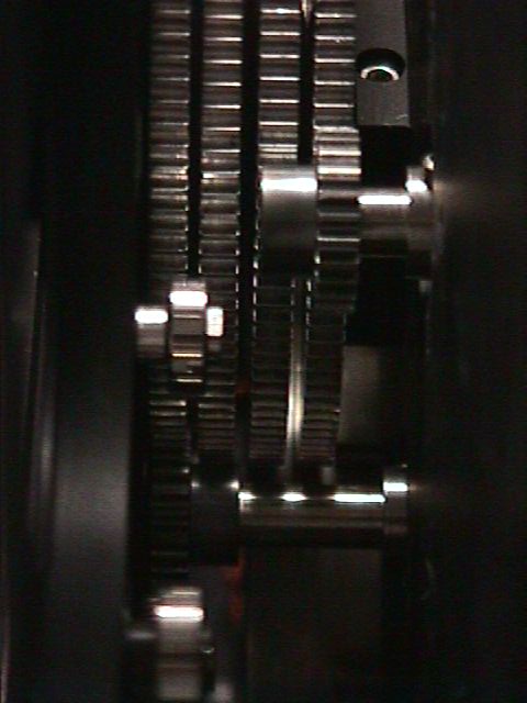
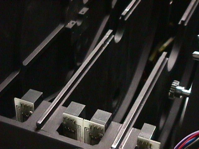
19. Remove Filter Wheel
A. Loosen set screws for drive gears on stepper motor shafts for the two upper motor shafts
1. Top view from back of Mimir shows upper right shaft drives first gear, upper left shaft drives second gear (counting 1st as closest to front of Mimir)
2. To remove drive gears, must walk gears off shafts and past meshing gears
4. Rotate motor shafts so flats point to large gears
B. Release screws holding filter wheel shaft capture blocks at front and back bulkhead ends
C. Remove capture blocks
D. Pull Filter Wheel stack, rotating wheels, especially POL wheel, as needed to demesh and remove FW stack
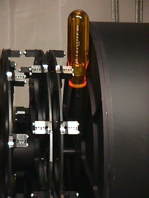
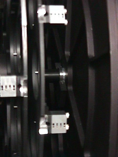
E. Pictures of FW shaft ends, showing spacer at back and bearing race and wave washers at front
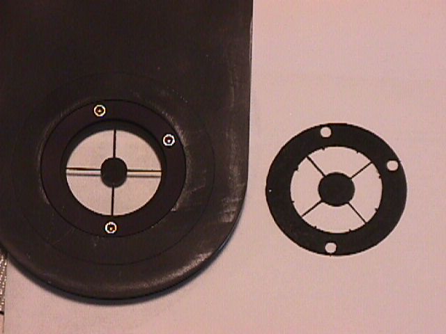
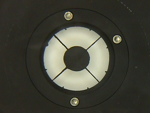
20. Pull Pupil Mask Holder
A. Mark front side
B. Deinstall mask holder from FW bulkhead
C. Compare old, new pupil masks
D. Deinstall old pupil mask
E. Install new pupil mask
1. Picture 124 – view from detector end
F. Reinstall pupil mask holder back in FW bulkhead
1. Screw heads face detector
21. Reinstall Filter Wheel Stack
A. Put in stack, then insert spacer between back bulkhead and back end of filter stack
B. Reinstall front, rear shaft capture blocks, screw in screws
C. Test that all filter wheels move properly
22. Reinstall Filters
A. Start by putting dark in home position in each wheel
1. “home” encoder blocks should be at detent location
B. reference new filter plan
C. Ks-1 filter shows some fingerprint-like features that do not dissolve with acetone
D. Installed Ks-2 (engineering sample) filter in FW2
E. Moved WG to FW3
F. Moved PK50-1 to FW2
G. Reset FW1 filters so home=dark
23. Realigned all Grism rotation angles
A. Rotated JHK by about 1 deg
B. Rotated LM by about 1.4 deg
C. Rotated SED by about 2.4 deg
24. Closed
up
A. Tested computer control of each filter wheel before closing cover
B. Retested computer control of each filter wheel after closing cover
1. Each wheel finds home
2. Each wheel turns freely for entire revolution (no sticking points)
25. Rewired Warm Bulkhead Heater System
A. Removed all heaters and heater blocks
B. Wired new, single dimmer into switch box
C. During testing, failed to warm 75 W heater as expected
1. Found wire for other 75 W heater was carrying voltage
2. Accidentally grounded that second heater wire to Mimir cart
a. Big spark, bang
b. Blew dimmer controller
i. Get 68 V output and no switch control
ii. Will replace dimmer controller
D. Reinstalled only one 75 W cartridge heater in a heater block nearest cold heat
1. Added 3 feet of wire, snaked it through the cold, then warm, and finally to hot zone
2. Should reduce frosting of bulkhead connector
3. Only active heater pins are “F” and “G” on TMX connector
E. Plug all open heater block threaded holes through cold bulkhead with screws
F.
NB – ended
up removing the 75 W heater to go to the new closed loop system
26. Purged cold head with 25-cycle Helium purge, including running head motor every 5
27. Swapped out helium compressor adsorber with “old” one from BU lab, prematurely removed.
A. Helium compressor Hour meter = 08957.1 hours
28. Added second copper strap from 2nd stage heater block to filter box
29. Clipped one of three 1/8” dia copper rods from sapphire heat transfer block to detector.
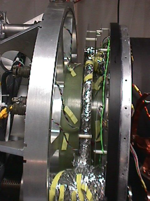
30. Removed “Beefeater” MLI from between SS floating shields between cold and warm bulkheads
A. Picture203
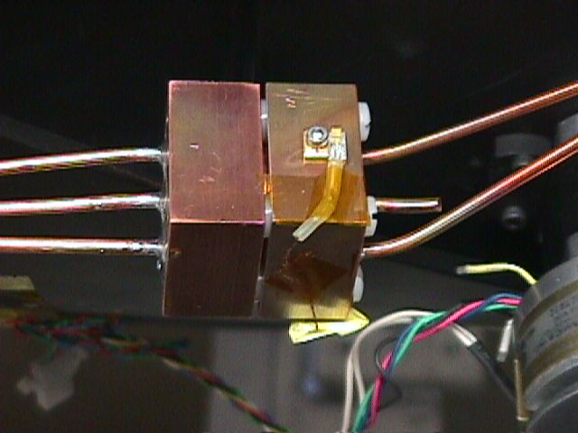
31. Designed, fabricated new system for selecting one of three units for closed loop temperature control by LS 331 Loop A
A. Modified 2nd stage heater/sensor block to hold:
1. a second heater cartridge (77 ohms = 32 W), called “R2”
2. a second thermal sensor, called “TA2”
3. originals now designated “R1” and “TA1” on drawings to distinguish them from “TA” which is now the input/output lines for the LS331
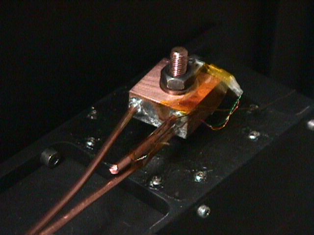
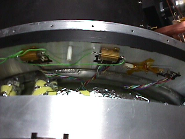
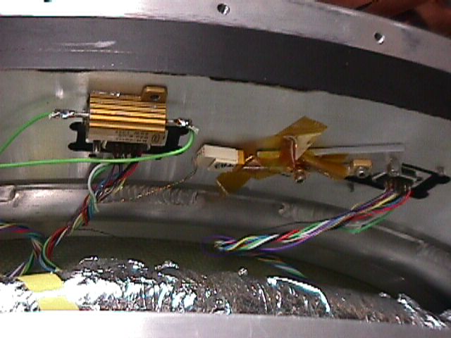
B. Created new closed-loop temperature system on cold bulkhead:
1. Removed cold bulkhead’s 75 W cartridge heater
2. Installed two 92 ohm 25 W resistors in parallel to become “R3” on cold bulkhead
a. Picture 208
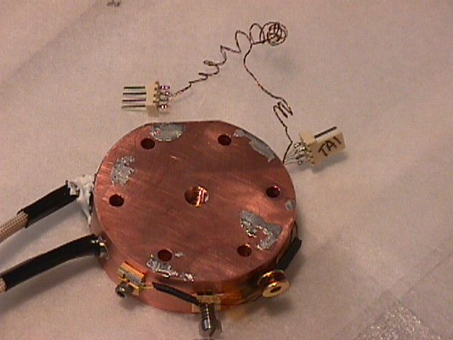
3. Installed temperature sensor on cold bulkhead (= “TA3”)
a. Picture 209
C.
Designed, fabricated new switch
panel to select which of the three inputs are seen by the
1. Switch panel installed on back of electronics box
a. Picture 211
2. Buzzed out all circuits, fixed errors
D. With Indium spacer/washers, reinstalled getter and its modified heater block onto the refrigerator 2nd stage
1. Picture 210
E. Reattached detector cooling strap system to getter
F. Tested all thermal sensor lines, then verified that all sensors work.
32. Verified that all motor systems work properly
33. Decker Unit
A. Removed copper thermal straps from slit car
B. Removed unused copper thermal strap from vicinity of decker car
1. Picture 109
C. Removed temp sensor from decker car to be secondary 2nd stage sensor
D. Cable clamped sensor wires out of the way of decker car and detent mechanism
E. Tested car motions under software control
1. Decker finds all limits fine
2. Marc’s “plate d home” goes home, but fails to find detent moving away from home. I think the problem is that if the detent is asserted when *at* home, the software can’t deal with it.
3. Same happens with “plate s home”
4. On sending the decker to/beyond the SR limit, under “plate d 200” it misses the SR signal (clearly seen on the display).
a. Later retest is OK, but resets step counter to 0 (home) again
b. Maybe this is a speed thing – signal not valid long enough to be caught??
5. However, doing the same with the slit unit “plate s 250” catches the SR signal.
a. But, when it did so, it reset the step counter to 0, thereby claiming it is at home!
6. I believe I am hearing steps being missed, also
a. Should have some acceleration term
i. Was RSA=10; RSM=800; RSD=600
ii. Trying 2; 1000; 600
(i) Works OK
7. Need to fix Marc’s software to deal with
a. Detent already present when at home
b. Not resetting step counter if SR hit
c. Slow down stepping to prevent missing SR or SL signals or speed up testing for signal (is code sleeping through signal? It is *not* latched…)
d. Or, have we queued up too many commands, so that when it stops on TC8 that it then goes on to the next command?
8. I find no problems with the decker unit sensing, so am closing up
34. Closed cryostat
A. Conventional – no problems
35. Initial Pumpdown and bake out
A. 3 hours pumping on 40mm line achieved about 0.5 torr
B. Backfilled with N2 to 20 torr
C. Set cold bulkhead heater to ramp to 320K
D. Detector ramp to 300 K
E. Left overnight
1. Pressure increased to about 43 torr
2. Cold bulkhead temperature only got to 315 K
36. Completion pump down
A. Added Mimir turbo and electric valve to pump line
B. Pumped out N2
1. Much slower – turbo and 25 mm line affect pumping speed
2. Also seems limited by this small pumping station (based on fore and aft pressures within the station)
C. Turned on Mimir turbo at 0.8 torr, which is quite high
1. Pumping speed is not impressive – 2 hrs to get to 0.4 torr – hope this speeds up..
D. Turned off cold bulkhead heater when it got to 318 K
E. Turned on getter heater, set ramp to go to 340 K